Wave maker based on hydraulic drive mode

A driving method and technology of wave generators, which are applied in the directions of engine components, fluid pressure actuating devices, mechanical equipment, etc., can solve the problem of large pressure loss, the hydraulic reversing valve can not meet the requirements of use, and can not meet the higher frequency of wave generators. requirements and other issues to achieve the effect of large traffic

Inactive Publication Date: 2014-05-21
NINGBO INST OF TECH ZHEJIANG UNIV ZHEJIANG
View PDF5 Cites 21 Cited by
  • Summary
  • Abstract
  • Description
  • Claims
  • Application Information

AI Technical Summary

Problems solved by technology

The reversing frequency of the electromagnetic reversing valve is determined by the operating frequency of the electromagnet, which is not easy to adjust, and its valve core can only move back and forth in a straight line, the response speed is slow, and the reversing frequency is not high
In addition, the valve port opening of the electromagnetic reversing valve is small, the pressure loss is large, and the flow rate is limited.
Although the flow rate of the electro-hydraulic directional valve is relatively large, its reversing frequency is lower than that of the electromagnetic directional valve, which makes it unable to meet the higher frequency requirements of the wave maker.
Therefore, in a wave maker that requires a higher frequency (such as when it exceeds 100Hz) and the reversing frequency needs to be adjusted (such as when the desired waveform of the water wave is more complex), the traditional hydraulic reversing valve cannot meet the requirements.

Method used


Image

  • Wave maker based on hydraulic drive mode
  • Wave maker based on hydraulic drive mode
  • Wave maker based on hydraulic drive mode

Examples


Embodiment Construction

[0041] The following will clearly and completely describe the technical solutions in the embodiments of the present invention with reference to the accompanying drawings in the embodiments of the present invention. Obviously, the described embodiments are some of the embodiments of the present invention, but not all of them. Based on the embodiments of the present invention, all other embodiments obtained by persons of ordinary skill in the art without making creative efforts belong to the protection scope of the present invention.

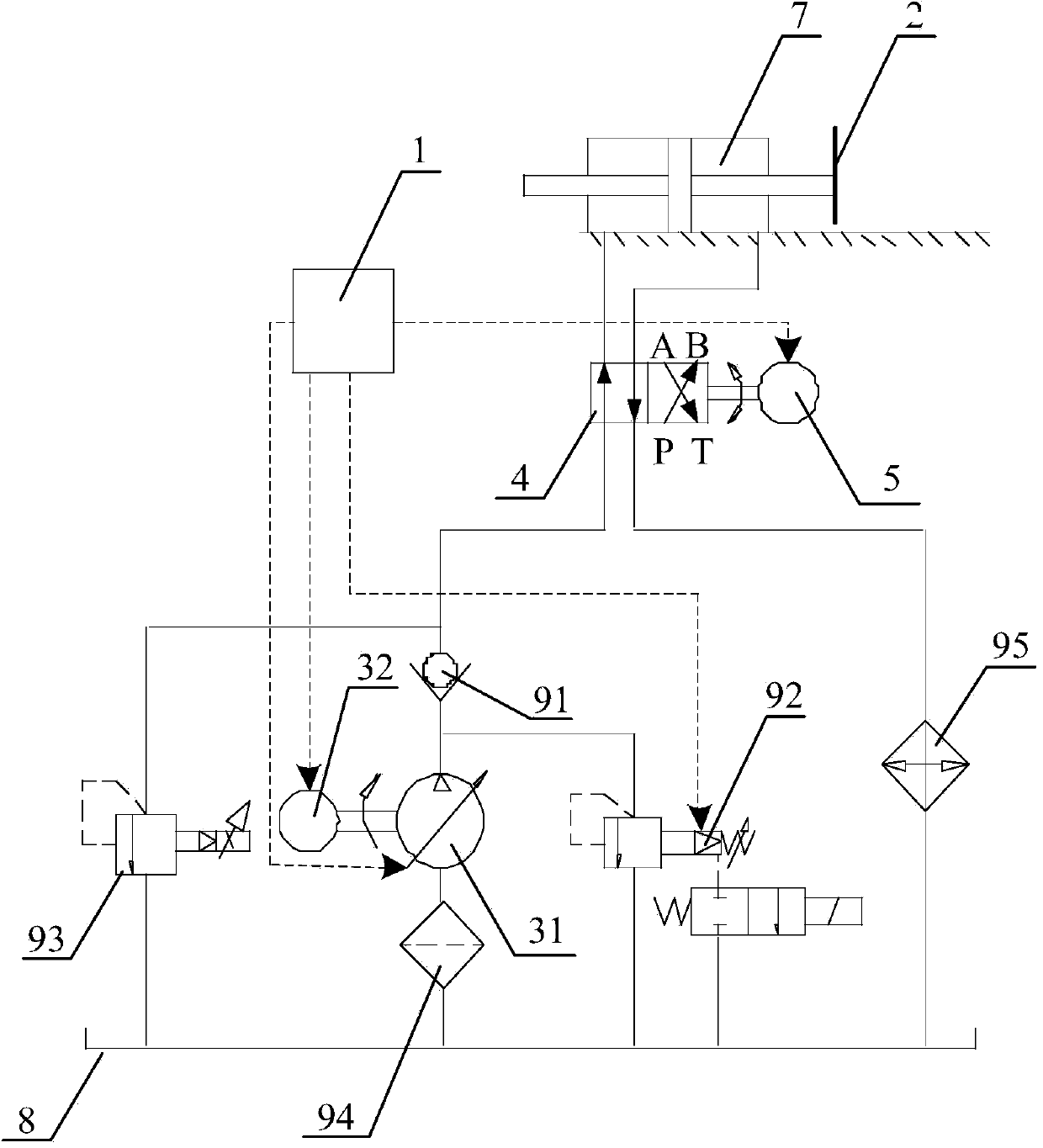
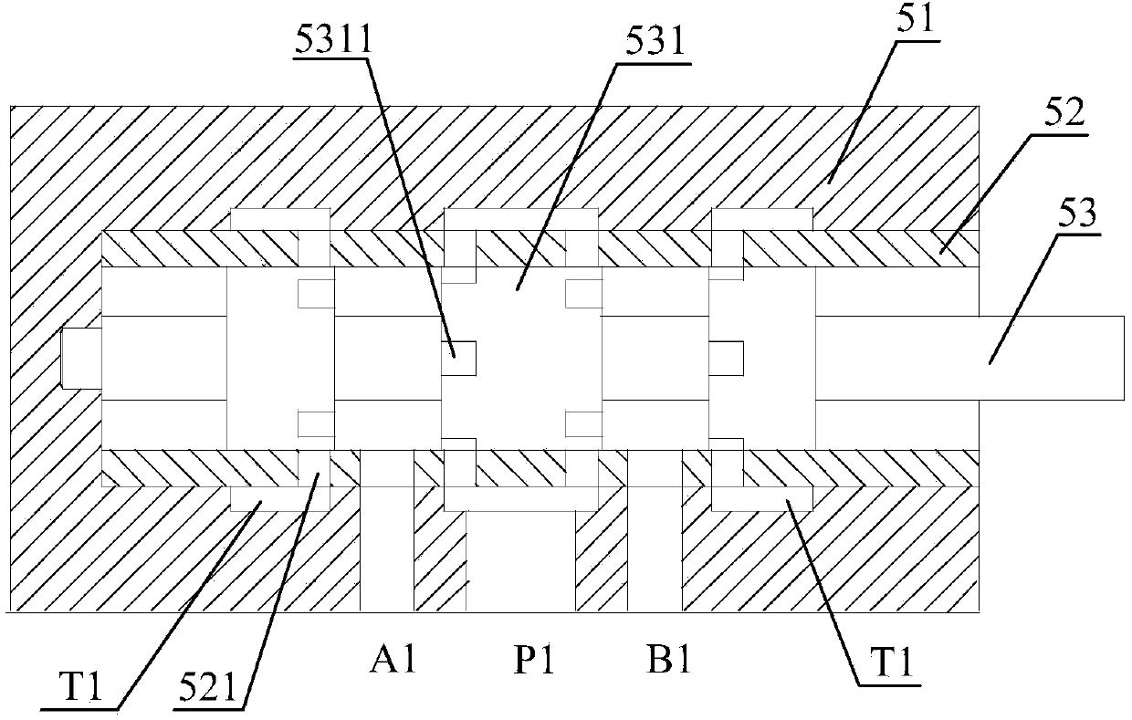
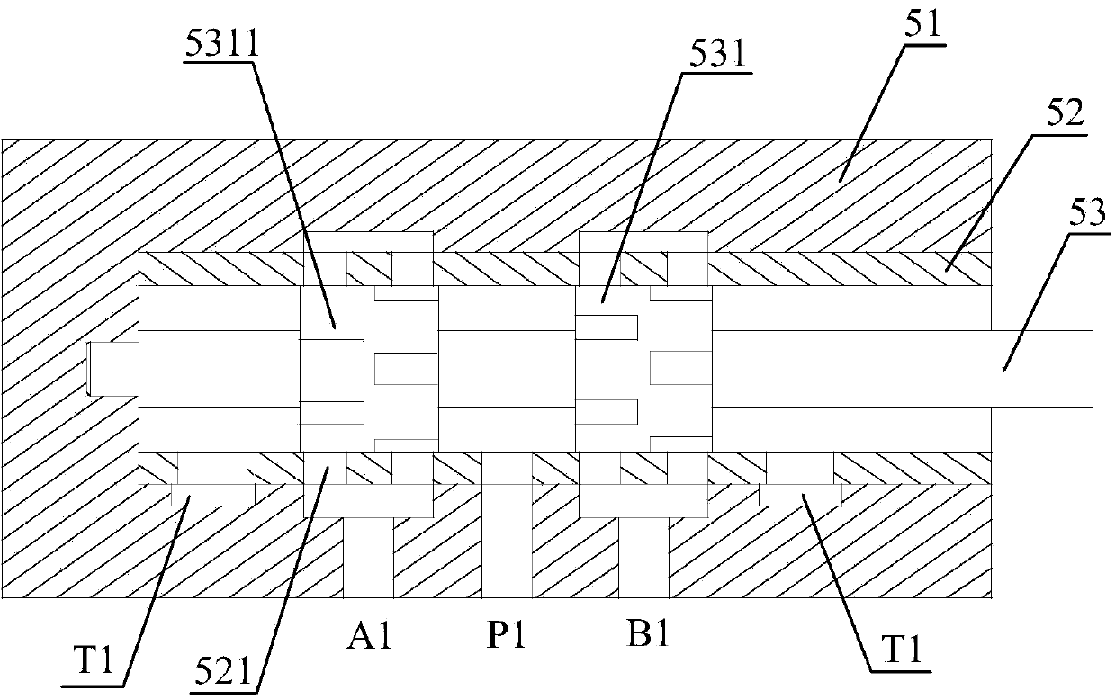
[0042] refer to Figure 1 to Figure 16 . A wave maker based on a hydraulic drive method includes a control system 1, a hydraulic drive system and a wave pusher 2. The hydraulic drive system includes a variable hydraulic pump 31 and a variable frequency motor 32 connected thereto, a hydraulic reversing valve 4, Three-phase hybrid stepper motor 5, double-acting excitation hydraulic cylinder 7, oil tank 8, check valve 91, electromagnetic overflow va...


PUM


Abstract

The invention relates to a wave maker based on a hydraulic drive mode. The wave maker comprises a control system, a hydraulic drive system and a wave pushing plate. The hydraulic drive system comprises a variable hydraulic pump, a frequency conversion motor, a hydraulic directional valve, a three-phase hybrid stepping motor, a double-acting shock excitation hydraulic cylinder, an oil tank, a check valve, an electromagnetic overflow valve, a proportional overflow valve, a cooler and a filter, wherein the frequency conversion motor is connected with the variable hydraulic pump; the wave pushing plate is fixedly installed at the output end of a piston rod of the double-acting shock excitation hydraulic cylinder. The hydraulic directional valve is a two-stage shock excitation valve formed by assembling a valve element rotary directional valve and a hydraulic-operated directional valve, the hydraulic-operated directional valve is a main stage valve, the valve element rotary directional valve is an auxiliary stage valve and comprises an auxiliary stage valve body, an auxiliary valve sleeve and an auxiliary valve element, and the auxiliary stage valve element is connected with the three-phase hybrid stepping motor. A control system is electrically connected with a displacement adjusting mechanism of the variable hydraulic pump, the three-phase hybrid stepping motor, the frequency conversion motor and the electromagnetic overflow valve. The wave maker can generate simulated water waves with various expected control laws by adjusting the working state of the hydraulic elements.

Description

technical field [0001] The invention belongs to the field of wave simulation, and in particular relates to a wave maker based on a hydraulic drive mode. Background technique [0002] In the fields of ships, ports, coastal engineering, ocean engineering, etc., wave-making technology is an important test technology, and the wave-making technology is simulated by the wave-making machine as an important laboratory device. The wave maker is composed of a control system, a drive system, and a wave pusher. Under the control of the control system, the drive system drives the wave pusher to move according to a certain control law, and the wave pusher pushes the water body to form various forms of simulated water waves. , used to study the effect of water waves on underwater structures such as ships, docks and dams. [0003] According to the different driving methods, wave generators can be divided into two categories: wave generators based on motor drive and wave generators based on...

Claims


Application Information

Patent Timeline
Patent Type & Authority Applications(China)
IPC IPC(8): E02B1/02G01M10/00F15B11/00F15B13/02F16K11/08
Inventor 刘毅程少科朱敏佳章聪龚国芳陈俊华
Owner NINGBO INST OF TECH ZHEJIANG UNIV ZHEJIANG
Why Eureka
Try Eureka