

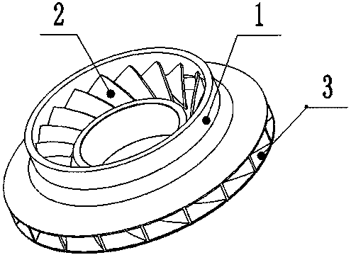
Enclosed impeller of centrifugal compressor
A centrifugal compressor, closed impeller technology, applied in mechanical equipment, non-variable capacity pumps, machines/engines, etc., can solve the problems of inability to guarantee the distribution of the outlet angle, difficult blade load adjustment, etc., to improve performance indicators, reduce Effect of Eddy Current Loss
- Summary
- Abstract
- Description
- Claims
- Application Information
AI Technical Summary
Problems solved by technology
Method used
Image

Examples
Embodiment 1
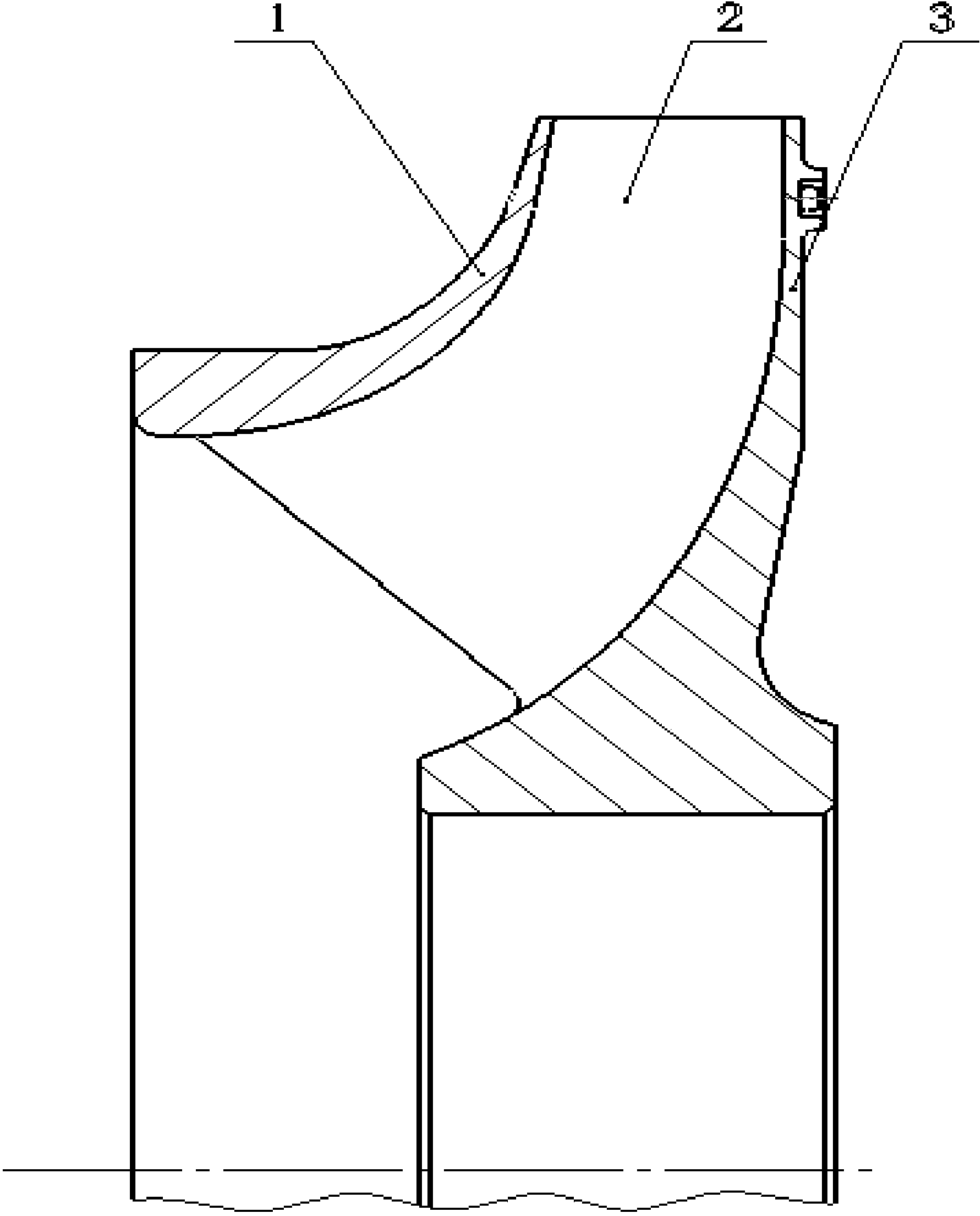
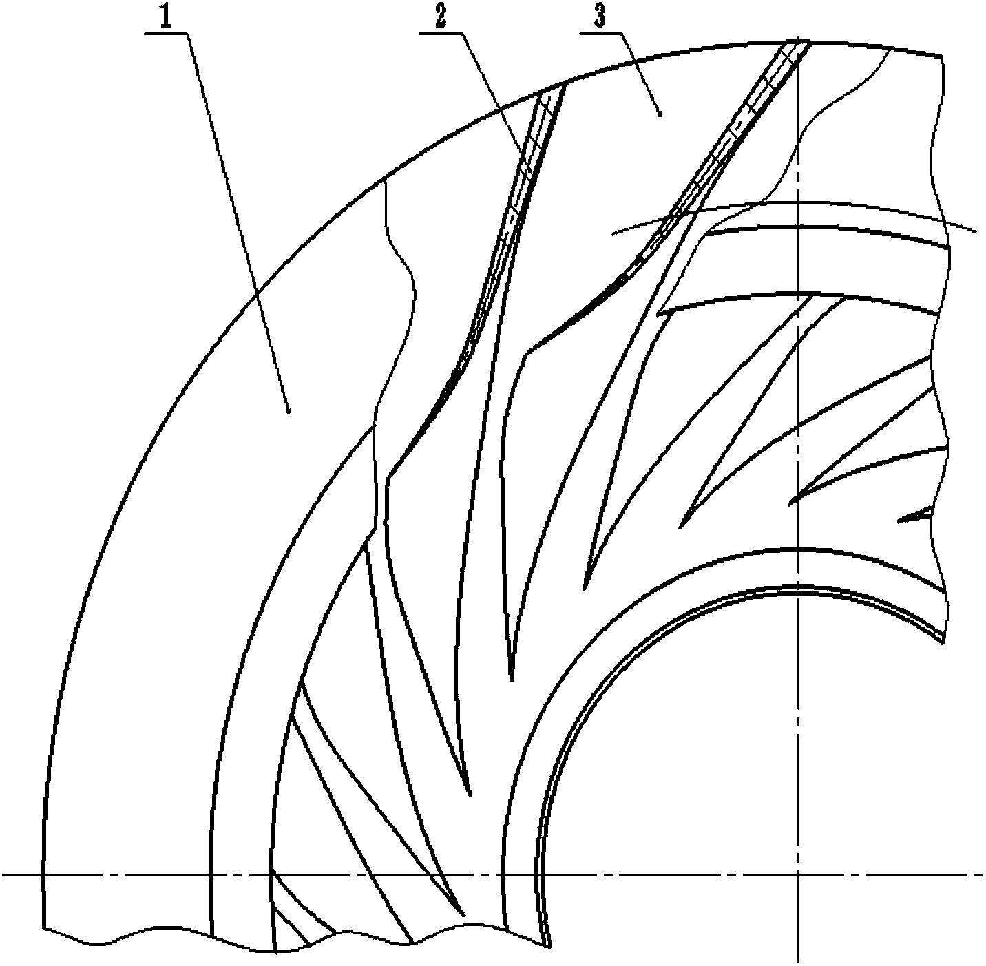
[0058] Using 15Cr2Mo1 pearlitic low-alloy heat-resistant steel forgings as blanks, the hub is first processed by a CNC lathe with an outer diameter of 600 mm, and then a blade is processed by a CNC milling machine. The average thickness of the blade is 4 mm; The lathe is used to process the roulette. The size of the roulette is 450 mm. The welding groove is milled out by a milling machine at the position of the roulette corresponding to the end of the blade. When welding, the blade is inserted into the corresponding groove, and then the welding robot is used for argon arc welding. The hub of the blade is welded to the wheel as a whole.
Embodiment 2
[0060] Using FV520B high-strength and high-toughness maraging steel forgings as blanks, first use CNC lathe to process the hub with an outer diameter of 800 mm, and then use CNC milling machine to process the blades. The average thickness of the blade is 8 mm; CNC lathe processes the roulette. The size of the roulette is 570 mm. Use a milling machine to mill out the welding groove at the position of the roulette corresponding to the end of the blade. When welding, insert the blade into the corresponding groove first, and then use the welding robot to argon arc welding. The hub with blades is welded to the wheel as a whole.
Embodiment 3
[0062] Using 15Cr2Mo1 pearlitic low-alloy heat-resistant steel forgings as blanks, the hub is first machined with a CNC lathe, the outer diameter of which is 700 mm, and then the blades are machined with a CNC milling machine. The average thickness of the blades is 6 mm; The lathe is used to process the roulette. The size of the roulette is 498 mm. The welding groove is milled out by a milling machine at the position of the roulette corresponding to the end of the blade. When welding, the blade is inserted into the corresponding groove, and then the welding robot is used for argon arc welding. The hub of the blade is welded to the wheel as a whole.
PUM
| Property | Measurement | Unit |
|---|---|---|
| The average thickness | aaaaa | aaaaa |
| Size | aaaaa | aaaaa |
| The average thickness | aaaaa | aaaaa |
Abstract
Description
Claims
Application Information