
X-ray focus tester based on slit method

An X-ray, tester technology, applied in the field of non-destructive testing, to achieve the effect of high radius accuracy

Inactive Publication Date: 2014-05-21
天津市医学堂科技有限公司
View PDF4 Cites 2 Cited by
  • Summary
  • Abstract
  • Description
  • Claims
  • Application Information

AI Technical Summary

Problems solved by technology

[0004] The diameter errors of the X-ray focus measured by the above-mentioned various X-ray focus detection devices are all on the order of millimeters. In addition, they can only detect larger focus diameters. Therefore, the existing X-ray focus detectors have certain limitations.

Method used

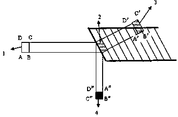

Image

  • X-ray focus tester based on slit method
  • X-ray focus tester based on slit method

Examples


Embodiment 1

[0016] Embodiment one: if figure 1 The test layout diagram of the X-ray focal point detection experiment is shown. A slit diaphragm is arranged on the X-ray path. The slit is formed by sandwiching a layer of plexiglass plate with a thickness of d between two heavy metal tungsten plates of sufficient thickness. d is much smaller than the spot size, the thickness of the tungsten plate can sufficiently attenuate the X-rays, and the black density distribution image i(x) with distinct layers will be received on the subsequent film.

[0017] Depend on figure 1 The geometric relationship of D 0 = [DL 1 -d(L 2 + L 1 )] / L 1 The experimental layout is to arrange a step device on the X-ray path, and place the film close to the step. During the experiment, a blurred step image will be obtained on the receiving film, and the step image contains the fuzzy information of the film system.

Embodiment 2

[0018] Embodiment 2: The focus size mainly depends on the shape and size of the cathode filament of the X-ray tube. The part of the anode target hit by electrons is called the actual focus; the projection of the actual focus on the ray window is called the effective focus, such as figure 2 , assuming that the electron beam is approximately parallel to the anode, and then using the principle of pinhole imaging to project the actual focus onto the film, the size of the effective focus can be obtained from the projection size on the negative according to the relevant formula.


PUM


Abstract

The invention discloses focus X-ray precision testing equipment used for the field of industrial radiation testing, more specially relates to an X-ray focus tester based on slit method, and belongs to the field of nondestructive automatic testing equipment. The X-ray focus tester based on slit method comprises a microfocus X-ray source, a radiation image receiver, an X-ray emission source, a multi-angle rotation three-dimensional testing device of the radiation image receiver, a four-axis moving platform of samples to be tested, and a computer and hierarchical control system. According to the X-ray focus tester, sizes of X-ray spots are determined via slit grating imaging, the line spread function and modulation transfer function (MTF) of the light source are obtained via slit imaging, and then the light spot size of the light source is determined based on a spatial frequency corresponding to MTF of 0.5. The X-ray focus tester based on slit method is nondestructive testing equipment of a new generation, is especially used for testing of electronic products and production testing of a plurality of medical facilities, and can be used in the fields of medical treatment, spaceflight, military, and industry.

Description

technical field [0001] The invention belongs to the technical field of nondestructive testing, and relates to an X-ray focus detector, in particular to an X-ray focus detector based on a slit method. Background technique [0002] Chinese Patent Announcement CN1736513A (Patent No. 200510060618.8) discloses a "positioning method of dynamic focus of gamma ray therapy equipment", which discloses a positioning method of dynamic focus of gamma ray therapy equipment. For gamma ray therapy, each frame rotates around the C axis with a worm gear and worm drive, and moves along the X axis with a screw drive. Movement in the Z direction. After installing the reference ball of the treatment head and the reference ball of the treatment bed, turn on the +SV power supply, so that the coordinates of the B and C axes are at 0. Position, the manipulating equipment moves along the X, Y and Z directions respectively, so that the reference ball of the treatment head and the reference ball of th...

Claims


Application Information

Patent Timeline
IPC IPC(8): G01N23/04A61N5/10
Inventor 刘婷婷
Owner 天津市医学堂科技有限公司
Learn More