Intelligent switch for zigbee technology

A technology of intelligent switch and technology, applied in the direction of electrical program control, comprehensive factory control, etc., can solve problems such as single function and sensor integration, and achieve the effect of enhancing scalability, avoiding waste, and reducing energy consumption

Inactive Publication Date: 2014-05-21
江苏博宏物联网科技有限公司
View PDF8 Cites 1 Cited by
  • Summary
  • Abstract
  • Description
  • Claims
  • Application Information

AI Technical Summary

Problems solved by technology

[0005] The purpose of the present invention is to provide a smart switch for zigbee technology, which is used to overcome the shortcomings of existing products that have a single function and cannot be integrated with existing air conditioners, security products, and various sensors. The multi-purpose interface module designed by it, Users only need to connect existing air conditioner controllers, security products, and various sensors with the products in this application through multi-purpose interfaces, and then realize the docking of remote wireless intelligent control equipment with air conditioners and security products

Method used


Image

  • Intelligent switch for zigbee technology
  • Intelligent switch for zigbee technology
  • Intelligent switch for zigbee technology

Examples


Embodiment 1

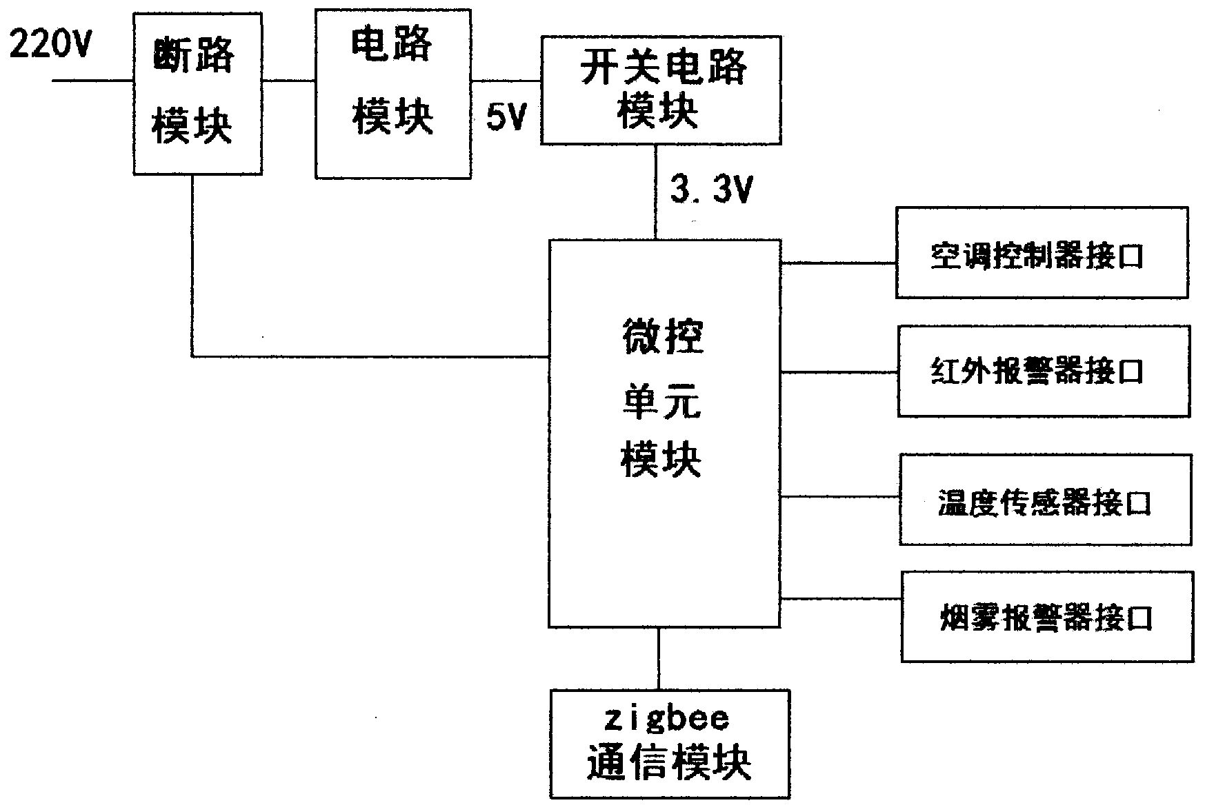
[0034] Embodiment 1 refers to Figure 1-9 , the smart switch for zigbee technology includes a zigbee communication module, a power module, a circuit breaker module, a micro control unit module, a switch circuit module, an air conditioner controller interface, an infrared alarm interface, a temperature sensor interface and a smoke alarm interface;

[0035] Micro control unit module, including CC2530 chip U3, first resistor R1, first capacitor C1 and second capacitor C2, the reset terminal RESET of CC2530 chip U3 is respectively connected to one end of the first resistor R1 and one end of the first capacitor C1, and the first resistor R1 The other end and the CC2530 chip U3 power supply terminal VCC are connected to a 3.3V power supply, the first capacitor C1 and the CC2530 chip U3 ground terminal are grounded, and the CC2530 chip U3 power supply terminal VCC is grounded through the second capacitor C2;

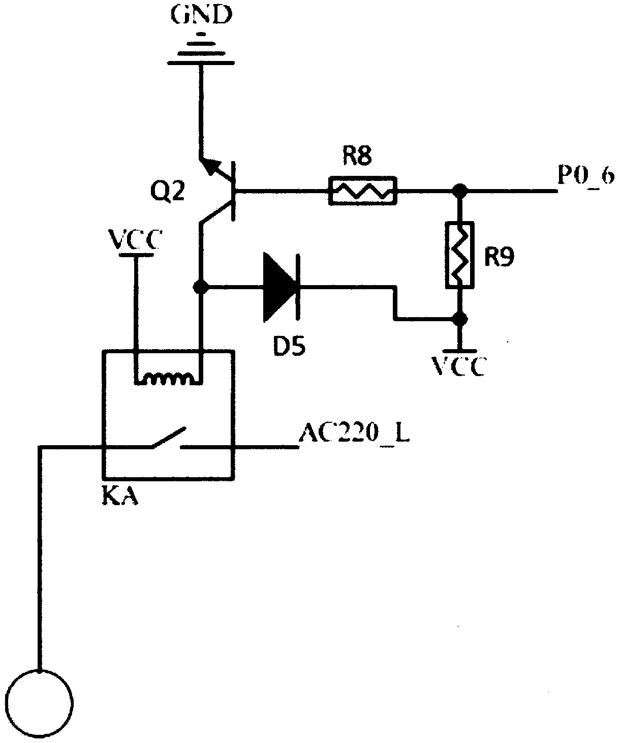
[0036] A switch circuit module, including a power interface P1, a three-te...

Embodiment 2

[0044] Embodiment 2 refers to Figure 10-13 , the smart switch for zigbee technology includes a zigbee communication module, a power module, a circuit breaker module, a micro control unit module, a switch circuit module, an illuminance sensor interface, a temperature sensor interface, a watt-hour meter detection interface and an infrared alarm interface, which are compatible with The difference of Embodiment 1 lies in the circuit of the circuit breaking module, the detection interface of the watt-hour meter and the interface of the illuminance sensor;

[0045] Illuminance sensor interface, including interface P2', interface P2'connection terminal 1 is connected to 3.3V DC, connection terminal 2 is connected to CC2530 chip clock signal terminal DCLOCK, connection terminal 3 is connected to CC2530 chip data transmission terminal DATA, connection terminal 4 is connected to CC2530 chip The digital reset terminal RESET is connected, and the connection terminal 5 is grounded;

[00...


PUM


Abstract

The invention discloses an intelligent switch for a zigbee technology. The intelligent switch comprises a zigbee communication module, a micro-control unit module, a switch circuit module and a multipurpose interface module, wherein the micro-control unit module is respectively connected with the zigbee communication module and the multipurpose interface module, and the switch circuit module is used for electrifying the connection of the micro-control unit module, the zigbee communication module and the multipurpose interface module. According to the intelligent switch, the defects that an existing product is single in function and can not be integrated with existing air conditioners, security products and various sensors; furthermore, due to the multipurpose interface module, a remote control wireless intelligent control device is butted with the air conditioners and the security products by connecting the existing air conditioners, security products and various sensors with the intelligent switch through the multipurpose interface module.

Description

technical field [0001] The invention relates to an intelligent switch, in particular to an intelligent switch used in zigbee technology, and belongs to the field of zigbee wireless communication. Background technique [0002] Zigbee is a low-power personal area network protocol based on the IEEE802.15.4 standard. The technology specified in this protocol is a short-distance, low-power wireless communication technology. The main features of ZigBee network are low power consumption, low cost, low speed, supporting a large number of nodes, supporting multiple network topologies, low complexity, fast, reliable and safe. Devices in a ZigBee network can be divided into three roles: Coordinator, Router, and EndDevice. As a short-distance wireless communication technology, zigbee has very strong applicability in the field of the Internet of Things because its network can conveniently provide users with wireless data transmission functions. [0003] Most of the existing wireless sm...

Claims


Application Information

Patent Timeline
Patent Type & Authority Applications(China)
IPC IPC(8): G05B19/418
Inventor 盛建国
Owner 江苏博宏物联网科技有限公司
Why Eureka
Try Eureka