An autonomous take-off and landing system for rotary-wing unmanned aerial vehicles based on a three-layer character-shaped multi-color landing pad
What is Al technical title?
Al technical title is built by PatSnap Al team. It summarizes the technical point description of the patent document.
An unmanned, zigzag-shaped rotor technology, applied in three-dimensional position/channel control and other directions, can solve the problems of limited navigation range of the vision system, blurred landing pad information, loss of landing pad information, etc., and achieve simplified image processing algorithms, small size, Lightweight effect
Active Publication Date: 2016-08-10
BEIHANG UNIV
View PDF6 Cites 1 Cited by
Summary
Abstract
Description
Claims
Application Information
AI Technical Summary
This helps you quickly interpret patents by identifying the three key elements:
Problems solved by technology
Method used
Benefits of technology
Problems solved by technology
Light, environment, and camera quality will all cause varying degrees of changes in the gray value of the pixels corresponding to the black and white markers in the image, making the gray value of the black part decrease and the gray value of the white part increase. Therefore, how to perform appropriate threshold segmentation processing on the landing pad image to extract the feature information of the landing pad becomes very important and the algorithm implementation is more complicated
In addition, limited by the size of the visual sign, if the rotor UAV is too far away from the landing pad, the information of the landing pad will be blurred and the measurement error will be increased. If it is too close, part of the landing pad pattern information will go out of the camera's field of view and cause information loss. Therefore, the navigation range of the vision system has certain limitations
Method used
Image
Click on the blue label to locate the original text in one second.
Reading with bidirectional positioning of images and text.
Examples
Embodiment Construction
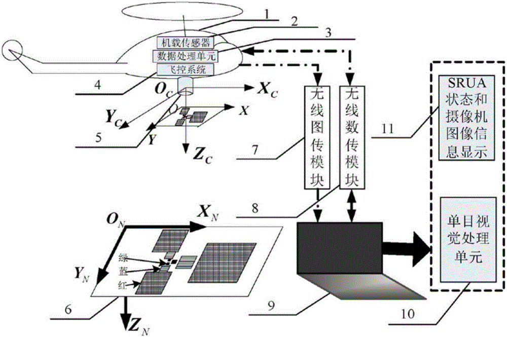
[0024] Such as figure 1 As shown, the present invention mainly comprises rotor UAV (1), airborne sensor (2), data processing unit (3), flight control system (4), airborne camera (5), ground landing pad (6), The wireless image transmission module (7), the wireless data transmission module (8) and the ground monitoring station (9); the airborne sensor (2), the data processing unit (3), and the flight control system (4) are respectively loaded on the rotor UAV (1), the ground monitoring station (9) is composed of a visual processing unit (10) and a display terminal (11).
[0025] The rotor UAV (1) is the carrier of the airborne sensor (2), the data processing unit (3) and the flight control system (4), and it is the research subject of the autonomous take-off and landing system of the rotor UAV;
[0026] The airborne sensors (2) are inertial measurement unit (IMU), global positioning system (GPS) receiver, magnetic compass, barometric altimeter, ultrasound;
[0027] The hardwar...
PUM
Abstract
Disclosed is a rotor unmanned aircraft independent take-off and landing system based on three-layer triangle multi-color landing ground. The system comprises a small rotor unmanned aircraft (SRUA), an onboard sensor, a data processing unit, a flight control system, an onboard camera, landing ground, a wireless image transmission module, a wireless data transmission module and a ground monitor station, wherein the onboard sensor comprises an inertial measurement unit, a global positioning system (GPS) receiver, a barometer, an ultrasound device and the like, the data processing unit is used for integrating sensor data, the flight control system finishes route planning to achieve high accuracy control over the SRUA, the onboard camera is used for collecting images of the landing ground, the landing ground is a specially designed landing point for an unmanned aircraft, the wireless image transmission module can transmit the images to a ground station, the wireless data transmission module can achieve communication of data and instructions between the unmanned aircraft and the ground station, and the ground station is composed of a visual processing unit and a display terminal. According to the rotor unmanned aircraft independent take-off and landing system based on the three-layer triangle multi-color landing ground, the reliability of SRUA navigation messages is guaranteed, the control accuracy of the SRUA is increased, costs are low, the application is convenient, and important engineering values can be achieved.
Description
technical field [0001] The invention relates to a vision-assisted navigation autonomous take-off and landing system of a rotor UAV, which can be used for autonomous navigation and control of the rotor UAV, and is especially suitable for military and civilian fields where the landing location of the rotor UAV is fixed and the navigation accuracy is high. . Background technique [0002] Rotor UAV has the advantages of small size, low cost, and flexible maneuverability. It can realize functions such as vertical take-off and landing, hovering, and ultra-low-altitude flight. It has a wide range of application prospects in military, civilian, and scientific research. [0003] The research on the take-off and flight technology of rotor UAV has been very in-depth, and good results have been obtained. However, the high-precision navigation control method in the landing stage is still a research hotspot, and it is still in its infancy in China. Accurate altitude information is the b...
Claims
Application Information
Patent Timeline
Application Date:The date an application was filed.
Publication Date:The date a patent or application was officially published.
First Publication Date:The earliest publication date of a patent with the same application number.
Issue Date:Publication date of the patent grant document.
PCT Entry Date:The Entry date of PCT National Phase.
Estimated Expiry Date:The statutory expiry date of a patent right according to the Patent Law, and it is the longest term of protection that the patent right can achieve without the termination of the patent right due to other reasons(Term extension factor has been taken into account ).
Invalid Date:Actual expiry date is based on effective date or publication date of legal transaction data of invalid patent.