Hydraulic oil tank

A technology of hydraulic oil tank and oil tank, applied in the hydraulic field, can solve problems such as shortening the life of hydraulic pump motor, and achieve the effect of increasing the flow path, facilitating replacement or installation, and improving heat dissipation

Active Publication Date: 2014-05-28
LIUZHOU SHUANGJI MACHINERY
View PDF8 Cites 16 Cited by
  • Summary
  • Abstract
  • Description
  • Claims
  • Application Information

AI Technical Summary

Problems solved by technology

Usually, in order to increase the way of hydraulic oil flow circulation to improve the effect of heat dissipation, air separation and precipitation of impurities, the hydraulic oil tank in the prior art is provided with a partition to make the distance between the oil suction pipe and the oil return pipe as short as possible. It may be farther away, but the through-holes set on the baffle to allow the oil to flow through the baffle are not ideal for removing the air in the hydraulic oil, which will shorten the life of the hydraulic pump and motor

Method used


Image

  • Hydraulic oil tank
  • Hydraulic oil tank
  • Hydraulic oil tank

Examples


Embodiment Construction

[0029] In order to further explain the technical means and effects of the present invention to achieve the intended purpose of the invention, the specific implementation, structure, characteristics and effects of the hydraulic oil tank proposed according to the present invention will be described in detail below in conjunction with the accompanying drawings and preferred embodiments. The description is as follows. In the following description, different "one embodiment" or "embodiment" do not necessarily refer to the same embodiment. Furthermore, the particular features, structures, or characteristics of one or more embodiments may be combined in any suitable manner.

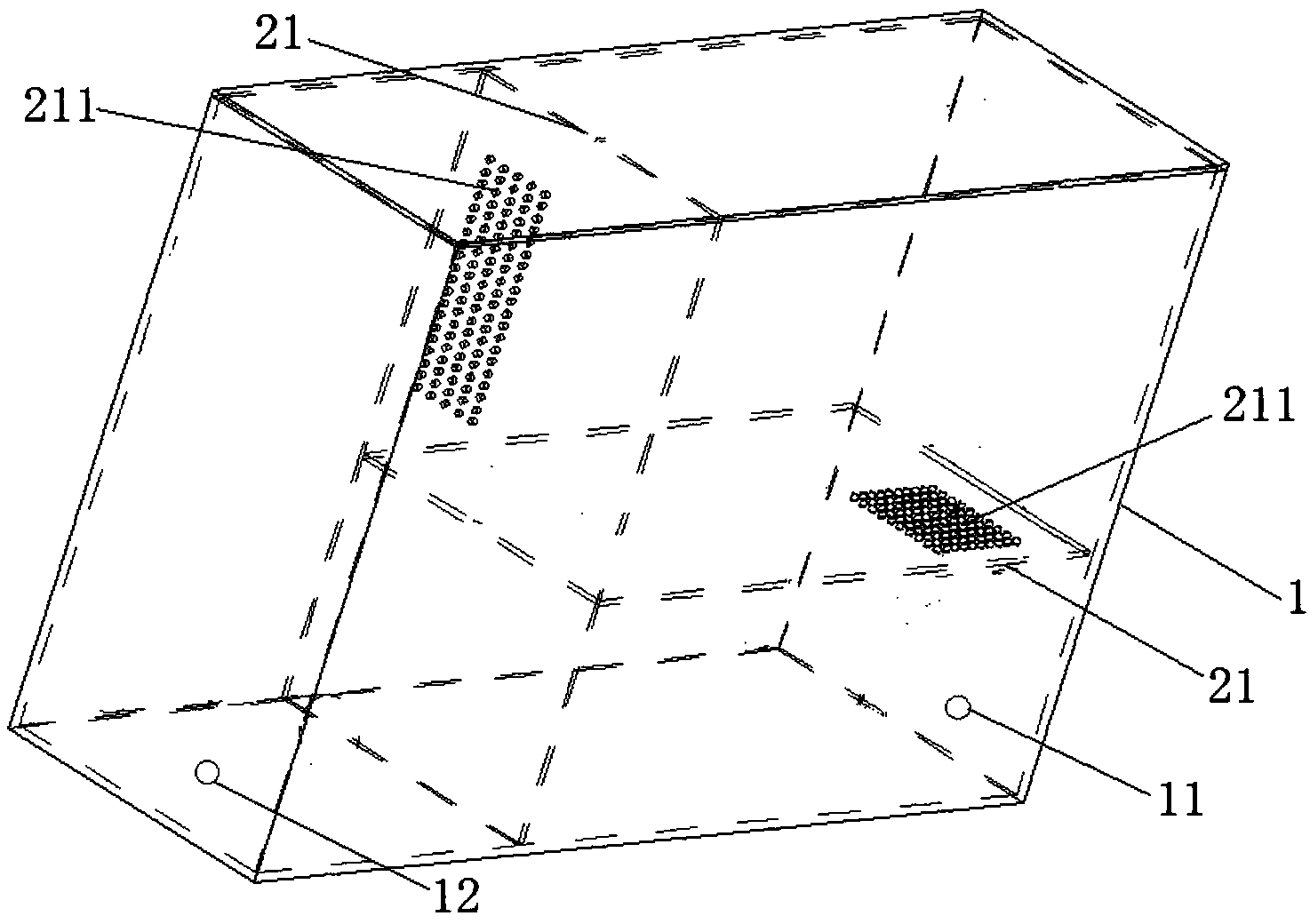
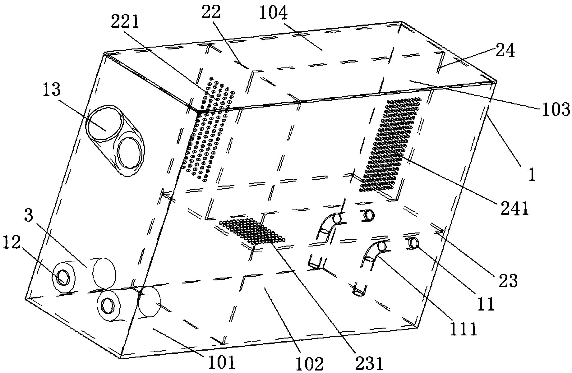
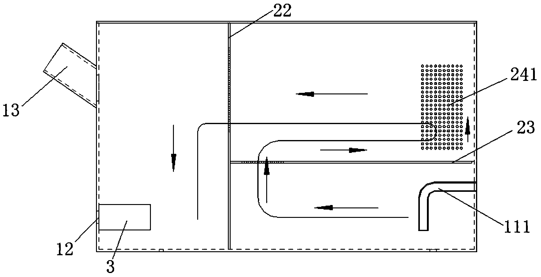
[0030] An embodiment of the present invention proposes a hydraulic oil tank, such as figure 1 As shown, the hydraulic oil tank includes an oil tank main body 1 and an isolation component arranged in the oil tank main body 1 . Wherein, the oil tank main body 1 is provided with an oil return port 11 and an oil s...


PUM


Abstract

The invention relates to a hydraulic oil tank, which comprises an oil tank body and an isolating component arranged in the oil tank body, wherein the oil tank body is provided with an oil return opening and an oil suction opening; the isolating component comprises at least two clapboards which divide the cavity of the oil tank body into three or more than three oil chambers; the oil return opening and the oil suction opening are positioned in two different oil chambers; all the clapboards are provided with meshes for allowing oil to pass through, so that the oil which enters the oil tank body by way of the oil return opening can pass through all the oil chambers in the oil tank body and then enters the oil suction opening; the size of each through hole which forms the mesh is big enough for the effect that air in the oil can be removed when the oil passes through the through holes. According to the hydraulic oil tank provided by the invention, effects of heat radiation, air separation and impurity precipitation are good, and bubbles in the hydraulic oil can be well removed.

Description

technical field [0001] The invention relates to the hydraulic field, in particular to a hydraulic oil tank. Background technique [0002] Compared with mechanical transmission and electric transmission, the hydraulic system has many advantages such as light weight, small size, small motion inertia, fast response, convenient operation and control, wide range of stepless speed regulation, and automatic overload protection. It has been widely used in various sectors of the national economy. [0003] As an important part of the hydraulic system, the hydraulic oil tank plays an important role. For example, the hydraulic oil tank is responsible for storing the oil required for the circulation of the hydraulic system, maintaining the working temperature of the hydraulic system, and separating the air and sediment mixed in the oil. . Usually, in order to increase the way of hydraulic oil flow circulation to improve the effect of heat dissipation, air separation and precipitation o...

Claims


Application Information

Patent Timeline
Patent Type & Authority Applications(China)
IPC IPC(8): F15B1/26F15B21/04
Inventor 郭健
Owner LIUZHOU SHUANGJI MACHINERY
Why Eureka
Try Eureka