Resolution detecting and calibrating method for ultrasonic microscope

A technology of ultrasonic microscope and calibration method, which is applied in the direction of material analysis, measuring device, and analysis material using sound wave/ultrasonic wave/infrasonic wave, which can solve problems such as defect detection ability, and achieve the effect of easy implementation and simple operation

Active Publication Date: 2014-05-28
BEIJING INSTITUTE OF TECHNOLOGYGY
View PDF7 Cites 16 Cited by
  • Summary
  • Abstract
  • Description
  • Claims
  • Application Information

AI Technical Summary

Problems solved by technology

[0005] The purpose of the present invention is to provide a test and calibration method for the detection resolution of an ultrasonic microscope, which is used to verify the horizontal and vertical defect detection capabilities of the ultrasonic microscope, and at the same time calibrate the detection results of the ultrasonic microscope through the corresponding calibration method to solve the ultrasonic detection process. The problem of objective evaluation of defect detection capabilities in medium and medium-sized defects makes the detection results of ultrasonic microscopes more accurate

Method used


Image

  • Resolution detecting and calibrating method for ultrasonic microscope
  • Resolution detecting and calibrating method for ultrasonic microscope
  • Resolution detecting and calibrating method for ultrasonic microscope

Examples


Embodiment Construction

[0014] The specific embodiment of the present invention is described in detail below:

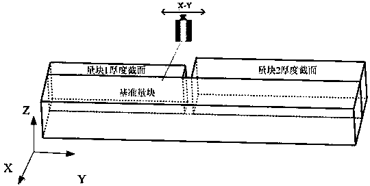
[0015] 1. If figure 1 As shown, when the ultrasonic scanning microscope is working, the computer triggers the pulse receiving / transmitting device to generate an excitation signal, which excites the piezoelectric chip to generate high-frequency ultrasonic waves. The sound wave is focused by the acoustic lens to the surface or inside of the sample to be tested, and reflection occurs at the discontinuity of the acoustic characteristics at the interface or inside of the sample. The reflected waves are picked up by piezoelectric elements and converted into electrical signals. The echo signal is sent to the data acquisition card after being amplified by the limiting and amplifying circuit, converted into a digital signal, and then digitally processed. At the same time, the computer controls the mechanical scanning platform to perform two-dimensional scanning control on the x-y horizontal plane ...


PUM

PropertyMeasurementUnit
depthaaaaaaaaaa
diameteraaaaaaaaaa
frequencyaaaaaaaaaa

Abstract

The invention belongs to the technical field of ultrasonic non-destructive detection, and relates to a resolution detecting and calibrating method for an ultrasonic microscope, which can be used for verifying transverse defect detection capability and longitudinal defect detection capability of an ultrasonic detection system, and enable the detection to be more accurate through calibrating a detection result of the ultrasonic microscope. The method comprises the following steps: etching a series of micron-size holes in the upper surface of an optical sheet glass through the laser micro-nano technology, wherein the dimension of the least micron-size hole that can be identified by ultrasonic micro imaging is the transverse detecting resolution; realizing transverse calibration by calculating a pixel compensation value through ultrasonic microscopic measurement for the longitudinal section of a standard gauge block; designing a glass wedge block sample and measuring the thickness with an acoustic time method, wherein the thickness of the thinnest water layer measured is the longitudinal detecting resolution; realizing longitudinal calibration by obtaining a linear fitting equation through analyzing a measured value and a theoretical calculating value. The method is simple to operate, is easy to realize, solves the problem of objective evaluation on ultrasonic defect detection capability, and enables the detection result of the ultrasonic microscope to be more reliable.

Description

1. Technical field [0001] The invention belongs to the field of ultrasonic detection, and relates to a resolution test and calibration method of an ultrasonic microscope, which is suitable for ultrasonic microscopic and ultrasonic C-scan detection. 2. Background technology [0002] Ultrasonic microscope is a new type of non-destructive testing instrument. It uses high-frequency focused ultrasonic waves to perform non-destructive testing on objects. It can detect the internal and sub-surface structures of objects with high precision and high sensitivity. It can observe the depth from the surface to tens of millimeters. Ultrasonic microscopic detection has the characteristics of high sensitivity, high resolution and intuitive images for the micron to hundreds of micron scale structures in the internal body. It has been widely used in the fields of electronics industry, medicine, material science and so on. [0003] The selection of high-frequency focused ultrasonic transducer ...

Claims


Application Information

Patent Timeline
Patent Type & Authority Applications(China)
IPC IPC(8): G01N29/30
Inventor 徐春广彭凯肖定国郭祥辉樊琼杨柳
Owner BEIJING INSTITUTE OF TECHNOLOGYGY
Why Eureka
Try Eureka