High-efficiency wideband power amplifier with band-pass filter response function

A technology of band-pass filter and power amplifier, which is applied in the direction of power amplifier, improved amplifier to expand bandwidth, impedance network, etc. It can solve the problems of poor performance of microstrip bandpass filter, loss of connecting microstrip line, and large circuit volume and other issues, to achieve good matching, to achieve broadband characteristics, the effect of small circuit size

Active Publication Date: 2014-05-28
SOUTH CHINA UNIV OF TECH
View PDF1 Cites 26 Cited by
  • Summary
  • Abstract
  • Description
  • Claims
  • Application Information

AI Technical Summary

Problems solved by technology

The power amplifier and the microstrip bandpass filter are usually first matched to 50Ω and then cascaded together. There are two main problems in this cascading method: 1. The connection of the microstrip line between the two circuit modules will introduce loss ; 2. The entire circuit is too large
According to "Y.C.Li, K.C.Wu, and Q.Xue, Power amplifier integrated with bandpass filter for long term evolution application, IEEE Microw. Wireless Compon. Lett., vol.23, no.8, pp.424–426, Aug. 2013." In the method adopted in the paper, a microstrip bandpass filter is integrated in the power amplifier as a quarter-wavelength impedance converter, however, the performance of the microstrip bandpass filter is not good, and due to the The microstrip bandpass filter can only achieve 90° phase transformation at the center frequency point, resulting in limited bandwidth
According to "K.Chen, J.Lee, W.J.Chappell, and D.Pertoulis, Co-design of highly efficient power amplifier and high-Q output bandpass filter, IEEE Trans.Microw.Theory Tech.,vol.61,no.11 ,pp.3940–3950,Nov.2013."In order to improve the performance of microstrip bandpass filter, high-Q cavity resonators are used, but this will make the circuit volume larger and complex, and relatively Bandwidth is only 3%

Method used


Image

  • High-efficiency wideband power amplifier with band-pass filter response function
  • High-efficiency wideband power amplifier with band-pass filter response function
  • High-efficiency wideband power amplifier with band-pass filter response function

Examples


Embodiment Construction

[0026] The implementation of the present invention will be further described below in conjunction with the accompanying drawings and examples, but the protection scope of the present invention is not limited to the following examples.

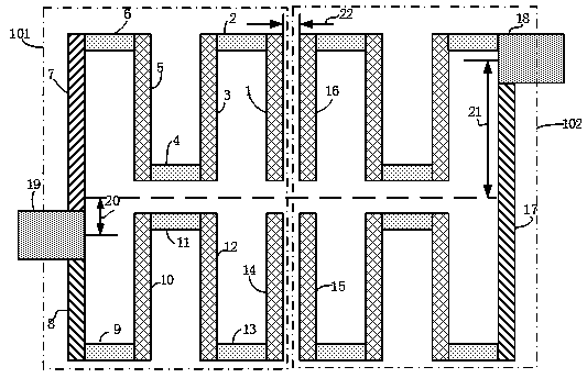
[0027] The high-efficiency broadband power amplifier with band-pass filter response proposed in the present invention mainly lies in its output matching circuit, that is, the microstrip band-pass filter provided by the present invention.

[0028] The microstrip line bandpass filter is composed of two half-wavelength resonators, and its structural schematic diagram is as follows figure 1As shown, they are called the input resonator 101 and the output resonator 102, or the input resonator 101 and the output resonator 102. The two half-wavelength resonators are both open-loop structures and are vertically symmetrical to each other. The input The resonator 101 is composed of the first microstrip line 1, the second microstrip line 2, the third micro...


PUM


Abstract

The invention discloses a high-efficiency wideband power amplifier with a band-pass filter response function. The high-efficiency wideband power amplifier comprises a DC biasing circuit, a power amplification transistor, an input match circuit and an output match circuit. A microstrip line band-pass filter with different port impedances and a section of tuning microstrip line are designed to be used as the output match circuit of the power amplifier, the function of the filtering is achieved, meanwhile, the circuits are made to have the band-pass filter response characteristic, and two transmission zeros are generated on the edge of a passband. Compared with a traditional cascade circuit of a power amplifier and a filter, due to the fact that the microstrip line band-pass filter is used as the output match circuit, the entire circuit is small in size, small in loss and wide in working band, and high edge selectivity is achieved due to the two transmission zeros. The high-efficiency wideband power amplifier with the high-pass filter response function is achieved, and testing result validation is provided.

Description

technical field [0001] The invention relates to the technical field of power amplifiers and microstrip line band-pass filters in wireless systems, in particular to a high-efficiency broadband power amplifier with band-pass filter response. Background technique [0002] Power amplifiers and microstrip bandpass filters are key components that affect the performance of RF transceivers, so there is a lot of research on how to improve them. For the power amplifier, its efficiency has a great influence on the power consumption and efficiency of the entire circuit system. How to improve the efficiency of the power amplifier is one of the focuses of research, and the microstrip bandpass filter is due to its ability to control harmonics And popular in high efficiency power amplifier design. [0003] The traditional research work is how to improve the performance of the two alone, but usually in practical applications, the microstrip bandpass filter is cascaded after the power amplif...

Claims


Application Information

Patent Timeline
Patent Type & Authority Applications(China)
IPC IPC(8): H03F3/20H03F1/42H03H7/38H03H7/12
Inventor 章秀银陈晓鸿高立
Owner SOUTH CHINA UNIV OF TECH
Why Eureka
Try Eureka