
Band-pass type bass loudspeaker box and adjusting method thereof

A sound box and bass technology, applied in the field of band-pass bass sound box and its adjustment, can solve the problems of large box volume, difficult to meet the diverse needs of bass sound box and sound power, uncontrollable box air flow rate, etc. Improve the effect of reducing volume, saving production costs and social resources, and saving material consumption

Inactive Publication Date: 2014-05-28
东莞凤合凰电声科技有限公司
View PDF6 Cites 7 Cited by
  • Summary
  • Abstract
  • Description
  • Claims
  • Application Information

AI Technical Summary

Problems solved by technology

[0007] The problem to be solved by the present invention is that the volume of the existing band-pass bass speaker box is relatively large, the air flow velocity of the box body is uncontrollable, and it is difficult to meet the defects of the sound color of the bass speaker and its sound power diversification. Subwoofer, which not only improves the accuracy and flexibility of the acoustic performance and quality of the low-frequency processing of the speaker, but also reduces the volume of the speaker, saving costs and resources

Method used


Image

  • Band-pass type bass loudspeaker box and adjusting method thereof
  • Band-pass type bass loudspeaker box and adjusting method thereof
  • Band-pass type bass loudspeaker box and adjusting method thereof

Examples


Embodiment 1

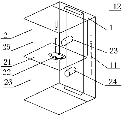
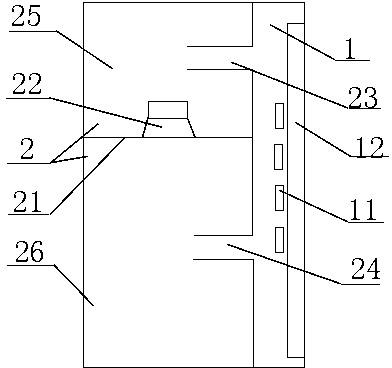
[0039] refer to figure 1 , 2 , the band-pass subwoofer of the present invention is a single-type band-pass subwoofer, that is, the basic structure of the present invention's variable application, which includes a subwoofer 2, which is provided with a horizontal partition 21 in the subwoofer 2, and a partition 21 is provided with a low-frequency speaker 22, and the partition 21 divides the subwoofer 2 into an upper box body and a lower box body. A higher low-frequency resonator 23 is arranged on the side wall of the upper box body. The lower low frequency resonator 24 is provided, the higher low frequency resonator 23 and the lower low frequency resonator 24 are located on the same longitudinal axis, so that the partition 21 divides the subwoofer 2 into a higher frequency subwoofer 25 and a lower frequency subwoofer 26.

[0040] The subwoofer 2 is provided with the outer section of the higher low frequency resonator 23 and the lower low frequency resonator 24 to connect the p...

Embodiment 2

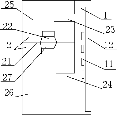
[0043] refer to image 3 , the bandpass subwoofer speaker of the present invention is figure 1 , 2 The push-pull bandpass subwoofer produced by the change of the bandpass subwoofer comprises a subwoofer 2, the subwoofer 2 is provided with a horizontal partition 21, the partition 21 is provided with a low frequency loudspeaker 22, the partition The bottom of 21 is provided with the double low frequency loudspeaker 27 whose electrical performance is the same as that of the low frequency loudspeaker 22 but acts as a supercharger. The high and low frequency resonator 23, the corresponding side wall of the lower box is provided with a lower low frequency resonator 24, and the higher low frequency resonator 23 and the lower low frequency resonator 24 are located on the same longitudinal axis, so that the partition 21 divides the subwoofer 2 It is divided into a higher frequency woofer 25 and a lower frequency woofer 26 .

[0044] The subwoofer 2 is provided with the outer secti...

Embodiment 3

[0047] refer to Figure 4 , the bandpass subwoofer speaker of the present invention is figure 1 , 2 Described basic structure changes from embodiment 1, that is, the composite band-pass subwoofer that is born from the single-type loading band-pass subwoofer, and it includes a subwoofer 2, and the subwoofer 2 is provided with a horizontal partition 21, the partition 21 is provided with at least two low-frequency loudspeakers 22 that can be paralleled. The partition 21 divides the subwoofer 2 into an upper box and a lower box, and a higher low-frequency resonator is provided on the side wall of the upper box. 23. A lower low-frequency resonator 24 is provided on the corresponding side wall of the lower box, and the higher low-frequency resonator 23 and the low-frequency resonator 24 are located on the same longitudinal axis, so that the partition 21 divides the subwoofer 2 into higher-frequency subwoofers. Speaker 25 and lower frequency subwoofer 26 .

[0048] The subwoofer...


PUM


Abstract

The invention relates to the technical field of electroacoustics, in particular to a band-pass type bass loudspeaker box and an adjusting method of the band-pass type bass loudspeaker box. The band-pass type bass loudspeaker box comprises a bass loudspeaker box body, wherein at least one horizontally-arranged partition plate is arranged in the bass loudspeaker box body, the partition plate is provided with at least one low-frequency loudspeaker, low-frequency resonators are arranged on the portions, above and below the partition plate, of the wall of the bass loudspeaker box body, and therefore the bass loudspeaker box body is divided into an upper low-frequency bass loudspeaker box body and a lower low-frequency bass loudspeaker box body. The bass loudspeaker box body is provided with voltage regulating bins, wherein the outer section of each low-frequency resonator is connected with the corresponding voltage regulating bin to form an acoustic resonance access, the voltage regulating bins are provided with damping holes, and sound absorption bodies are arranged in the voltage regulating bins. The number of the low-frequency loudspeakers and the combination mode of the low-frequency loudspeakers can be increased according to requirement of acoustic characteristics. The damping value and the Q value of the bass loudspeaker box are adjusted respectively by means of adjusting the total area of the damping holes and the sound absorption bodies. By means of the adjusting method, the low-frequency processing acoustic performance of the band-pass type bass loudspeaker box and the quality accuracy and the flexibility of the band-pass type bass loudspeaker box are improved. Since the band-pass type bass loudspeaker box is small in volume, cost can be reduced.

Description

[0001] technical field [0002] The invention relates to the field of electro-acoustic technology, in particular to a band-pass subwoofer sound box and an adjustment method thereof. Background technique [0003] From the perspective of the acoustic structure of the speaker box, since the open-back speaker appeared in 1924, the current acoustic structure applications of speakers mainly include closed and open. There are fewer types of closed speakers, mainly air cushion and push. There are two pull styles. There are many types of vented speakers, such as inverted, two-stage inverted, empty paper cone, labyrinth, bandpass, pipe, rear horn, 1 / 4 wavelength loaded, transmission line, Colton formula and so on. [0004] The common feature of open-type speakers is to use the speaker as the drive to resonantly couple the air in the box cavity with the resonator (usually called an inverted tube), so as to maximize the drive energy of the speaker into the resonance energy of the box ...

Claims


Application Information

Patent Timeline
Patent Type & Authority Applications(China)
IPC IPC(8): H04R1/20
Inventor 陈东红
Owner 东莞凤合凰电声科技有限公司
Learn More