Aligning and load reducing linear motor oil well pump

A linear motor and oil pump technology, applied in the direction of pumps, pump components, mechanical equipment, etc., can solve the problems of wearing the mating surface of the plunger and the pump barrel, increasing the pump barrel and the plunger, and large friction resistance, etc. Pump efficiency, reduced fit clearance, and small compressive load

Inactive Publication Date: 2014-06-04
CSIC ZHONGNAN EQUIP
View PDF0 Cites 0 Cited by
  • Summary
  • Abstract
  • Description
  • Claims
  • Application Information

AI Technical Summary

Problems solved by technology

[0002] Because the linear motor pumping system has the advantages of high efficiency and energy saving compared with the traditional beam pumping unit system, it has attracted more and more attention and attention from oil fields in recent years. As the key working part of the system, the linear motor oil well pump has also appeared in various structural forms, and its technology is also being continuously improved and improved, but there are still some deficiencies, for example, with two different diameter pump barrels and plunger sleeves The linear motor oil well pump with the linear motor installed at the lower part of the pump has a more reasonable structure than the single-barrel single-piston pump. Although the linear motor mover does not lift the liquid in the column during its upward stroke, the disadvantage is that the two A series-connected combined pump barrel and two series-connected combined plungers are assembled together by multiple parts in series. It is difficult to achieve concentricity during processing and assembly. If the concentricity is not good, the combined plunger and combined pump barrel Relative movement will generate a large frictional resistance, quickly wear the mating surface of the plunger and the pump barrel, and sometimes even cause the pump to be stuck, and may also bend the linear motor mover, causing serious failures
To reduce this friction resistance, the traditional method is to increase the gap between the pump barrel and the plunger, but this will increase the leakage of the pump and reduce the pump efficiency.

Method used


Image

  • Aligning and load reducing linear motor oil well pump

Examples


Embodiment Construction

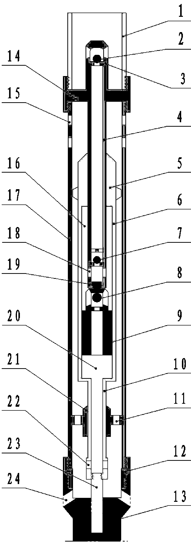
[0018] The structure of the present invention is as figure 1 Shown: a self-aligning and load-reducing linear motor oil well pump, mainly composed of a working pump barrel assembly, a working plunger assembly, an upper coupling, an upper oil outlet valve, an aligning joint, a guide plunger, an outer cylinder, and a linear motor, etc. , is characterized in that: the upper oil outlet valve 2 is connected to the upper part of the upper coupling 14, the small diameter plunger 4 is connected to the lower end of the upper coupling 14, and is located in the outer cylinder 17; the working plunger assembly consists of the small diameter plunger 4, the lower oil outlet valve 7. Self-aligning joint 19, oil inlet valve 8, and large-diameter plunger 9. The upper end of the outer cylinder 17 is connected with the upper coupling 14, and the lower part is connected with the linear motor stator 13 through the lower joint 12. The inner wall of the lower part of the outer cylinder 17 is installed ...


PUM


Abstract

An aligning and load reducing linear motor oil well pump is used for extraction of crude oil. The pump is mainly composed of a working pump cylinder assembly, a working plunger assembly, a aligning connector, a guiding plunger, an outer pipe and a linear motor, wherein the guiding plunger at the lower end of the pump cylinder assembly moves in a strengthening cylinder, and it is guaranteed that the pump cylinder assembly is aligned with the center when moving; large-diameter and small-diameter plungers are connected through the universal aligning connector, decentraction caused by machining and assembling is eliminated, the plunger assembly and the pump cylinder assembly can move relative to each other more smoothly, abrasion to the pump cylinder and the plungers is reduced, running resistance is reduced, pump blocking faults are avoided, and therefore loads and energy consumption of the linear motor are reduced, the efficiency is improved, and the oil extraction technology of the linear motor can be popularized easily.

Description

technical field [0001] The invention belongs to oil production equipment for mechanical exploitation in the petroleum industry, and in particular relates to a double-pump cylinder and double-plunger oil well pump driven by a linear motor. Background technique [0002] Because the linear motor pumping system has the advantages of high efficiency and energy saving compared with the traditional beam pumping unit system, it has attracted more and more attention and attention from oil fields in recent years. As the key working part of the system, the linear motor oil well pump has also appeared in various structural forms, and its technology is also being continuously improved and improved, but there are still some deficiencies, for example, with two different diameter pump barrels and plunger sleeves The linear motor oil well pump with the linear motor installed at the lower part of the pump has a more reasonable structure than the single-barrel single-piston pump. Although the ...

Claims


Application Information

Patent Timeline
IPC IPC(8): F04B47/06F04B53/16F04B53/12F04B53/14F04B53/00
Inventor 高宏张元圆唐裔振陈向灵刘建魁许家勤
Owner CSIC ZHONGNAN EQUIP
Why Eureka
Try Eureka