Secondary cooling method and secondary cooling device for continuous casting machine

A secondary cooling and casting machine technology, which is applied in the field of secondary cooling devices, can solve problems such as the decrease in the rigidity of the backing roll, the inability to fully support the slab, and the possibility of bulging, etc., to achieve the effect of improving cooling uniformity

Active Publication Date: 2014-06-04
NIPPON STEEL CORP
View PDF7 Cites 15 Cited by
  • Summary
  • Abstract
  • Description
  • Claims
  • Application Information

AI Technical Summary

Problems solved by technology

However, if the roll diameter of the back-up roll is reduced, not only the rigidity of the back-up roll will decrease, but also the bearings for supporting the both ends of the back-up roll will also be miniaturized, so that the slab cannot be supported sufficiently, resulting in the possibility of swelling. also become higher

Method used


Image

  • Secondary cooling method and secondary cooling device for continuous casting machine
  • Secondary cooling method and secondary cooling device for continuous casting machine
  • Secondary cooling method and secondary cooling device for continuous casting machine

Examples


no. 1 approach

[0052] 1.1. Overall structure of continuous casting machine

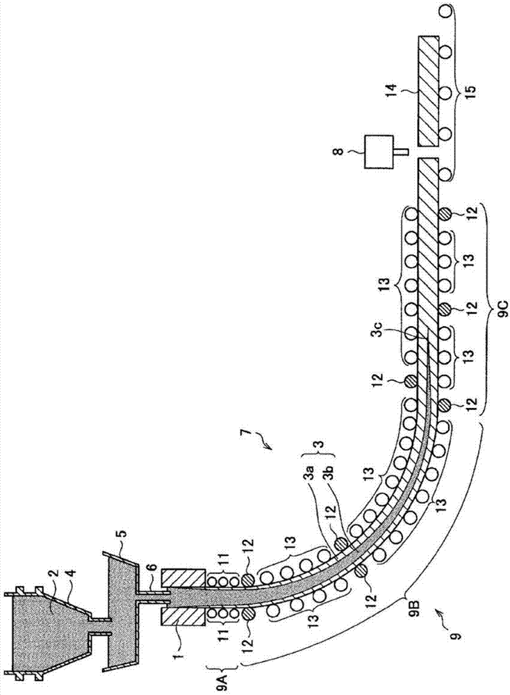
[0053] First, refer to figure 1 , the overall structure of the continuous casting machine according to the first embodiment of the present invention will be described. figure 1 It is a side sectional view showing the continuous casting machine of this embodiment.

[0054] Such as figure 1 As shown, the continuous casting machine is an apparatus for continuously casting a molten metal 2 (for example, molten steel) using a continuous casting mold 1 to manufacture a slab 3 such as a slab. The above-mentioned continuous casting machine has a casting mold 1 , a ladle 4 , a tundish 5 , a dipping nozzle 6 , a secondary cooling device 7 , and a billet cutter 8 .

[0055] The ladle 4 is a movable container for transferring the molten metal 2 to the tundish 5 from the outside. The ladle 4 is arranged above the tundish 5 , and the molten metal 2 inside the ladle 4 is supplied to the tundish 5 . The tundish 5 is disposed a...

no. 2 approach

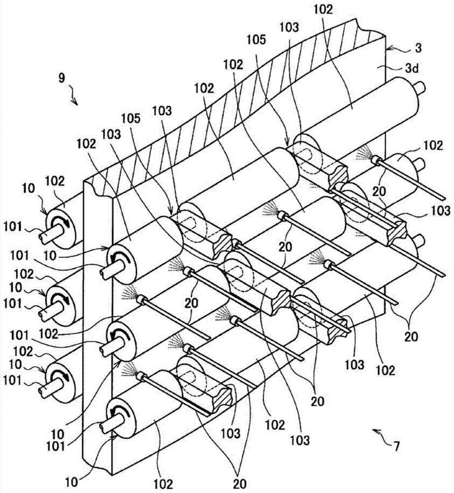
[0136] Next, the roll shape and nozzle arrangement of the secondary cooling device 7A of the continuous casting machine according to the second embodiment of the present invention will be described. Compared with the first embodiment, the second embodiment is different in that two split rolls are used, and the grooves of the back-up roll 10 through which the cooling water can flow In addition to the bearing part 103 between them, there are slits for water passage formed on the peripheral surface of each divided roller part 102, and other functional structures are the same as those of the above-mentioned first embodiment.

[0137] Figure 11 It is a front view showing the arrangement of the backup roll 10 and the nozzle 20 of the secondary cooling device 7A of the second embodiment. Such as Figure 11 As shown, each backup roll 10 is composed of two divided rolls, and has two divided roll parts 102A, 102B and one bearing part 103 provided between the two divided roll parts 102A...

no. 3 approach

[0148] Next, the roll shape and nozzle arrangement of the secondary cooling device 7B of the continuous casting machine according to the third embodiment of the present invention will be described. Compared with the first embodiment, the third embodiment is different in that two split rolls are used, and a plurality of thin slits for water passage are formed on the peripheral surface of the split roll portion 102 of the backup roll 10, and other functional structures It is the same as the first embodiment described above.

[0149] Figure 12 It is a front view showing the arrangement of the backup roll 10 and the nozzle 20 of the secondary cooling device 7B of the third embodiment. Such as Figure 12 As shown, each backup roll 10 is composed of two divided rolls, and has two divided roll parts 102A, 102B and one bearing part 103 provided between these two divided roll parts 102A, 102B. The bearings 103 respectively provided on the upstream backup roll 10 (upper roll) and th...


PUM


Abstract

This secondary cooling device for a continuous casting machine is provided with a plurality of pairs of support roller and a plurality of nozzles, and each support roller has: a plurality of roller sections split in the widthwise direction of a cast strand; and grooves provided between the roller sections. The grooves provided to each upstream-side support roller and downstream-side support roller adjacent in the direction of conveyance are disposed offset from each other in the widthwise direction. A first nozzle among the plurality of nozzles is disposed at a first nozzle position set between a roller section provided to an upstream-side support roller and a groove provided to a downstream-side support roller.

Description

technical field [0001] The invention relates to a secondary cooling device and a secondary cooling method of a continuous casting machine. [0002] this application claims priority based on Japanese Patent Application No. 2011-249762 for which it applied to Japan on November 15, 2011, and uses the content here. Background technique [0003] In the secondary cooling zone under the casting mold of the continuous casting machine, while raising a plurality of pairs of back-up rolls to support and transport the slab pulled out from the lower end of the mold, spray cooling from spray nozzles arranged between two adjacent back-up rolls Water (or a mixture of cooling water and air) to cool the strand. [0004] Conventionally, in the above-mentioned continuous casting machine, in order to increase the speed of pulling out the slab and suppress the heaving of the slab, a method of shortening the roll distance by using small-diameter rolls as the above-mentioned back-up rolls has been...

Claims


Application Information

Patent Timeline
Patent Type & Authority Applications(China)
IPC IPC(8): B22D11/124B22D11/128B22D11/22
CPCB22D11/225B22D11/124B22D11/1246B22D11/128
Inventor 山崎伯公嶋省三恒成敬二奥村恭司土岐正弘大谷康彦林聪
Owner NIPPON STEEL CORP
Why Eureka
Try Eureka