X-ray anti-scatter grid lattice structure, detector device and medical image system

A grid structure, anti-scattering technology, applied in the field of medical imaging, can solve the problems of high manufacturing cost and complicated process, and achieve the effect of reducing manufacturing cost and difficulty

Active Publication Date: 2014-06-11
SHANGHAI UNITED IMAGING HEALTHCARE
View PDF13 Cites 12 Cited by
  • Summary
  • Abstract
  • Description
  • Claims
  • Application Information

AI Technical Summary

Problems solved by technology

[0010] In order to overcome the shortcomings of the X-ray anti-scatter grid structure in the above-mentioned prior art, such as complex process and high manufacturing cost, the present invention provides an X-ray anti-scatter grid structure with simple process and low manufacturing cost

Method used


Image

  • X-ray anti-scatter grid lattice structure, detector device and medical image system
  • X-ray anti-scatter grid lattice structure, detector device and medical image system
  • X-ray anti-scatter grid lattice structure, detector device and medical image system

Examples


no. 1 example

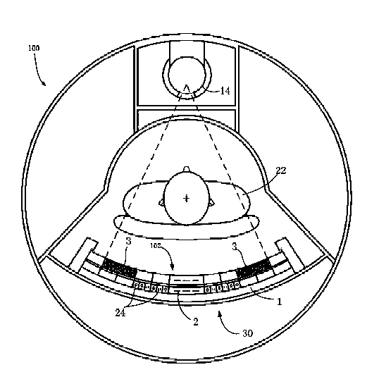
[0040] figure 1 is a schematic axial view of a Computed Tomography (CT) system 100 (here, as an example of a medical imaging system) having an X-ray anti-scatter grid structure 102 according to an embodiment of the present invention. like figure 1 As shown, the CT system 100 includes an X-ray emission source 14 and a detector arrangement 30 . The detector arrangement 30 includes an X-ray anti-scatter grid structure 102 and an X-ray detector 2 . The X-ray detector 2 includes an X-ray detector substrate 1 and a plurality of scintillation crystals 24 . During the scanning and imaging process, the X-ray emission source 14 emits X-rays. After the X-rays penetrate the human body 22 , they pass through the anti-scatter grid array module 3 and are received by the scintillation crystals 24 of the X-ray detector 2 . The X-ray anti-scatter grid structure 102 includes an anti-scatter grid array module 3 for absorbing scattered X-rays while absorbing as little effective X-rays as possib...

no. 2 example

[0056] Below, refer to Figure 8 and Figure 9 The X-ray anti-scatter grid structure 202 according to the second embodiment of the present invention is described.

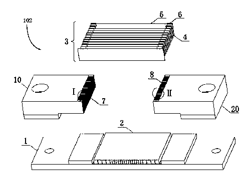
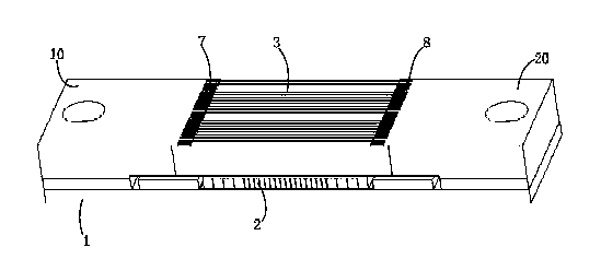
[0057] Figure 8 It is a schematic exploded perspective view of the X-ray anti-scatter grid structure 202 and the X-ray detector 2 according to the second embodiment of the present invention. Figure 9 It is a schematic perspective view of the X-ray anti-scatter grid structure 202 and the X-ray detector 2 according to the second embodiment of the present invention. exist Figure 8 and 9 , the same components as those of the first embodiment described above have the same reference numerals. Meanwhile, the same components as those of the first embodiment described above will not be described repeatedly in this embodiment. like Figure 8 and 9 shown, with the X in the first embodiment

[0058] Different from the ray anti-scatter grid structure 102 , the X-ray anti-scatter grid structure 202 of the second embo...

no. 3 example

[0063] Below, refer to Figure 10 The X-ray anti-scatter grid structure 302 according to the third embodiment of the present invention is described.

[0064] Figure 10 It is a schematic diagram showing the positional relationship between the X-ray anti-scatter grid structure 302 and the X-ray detector 2 according to the third embodiment of the present invention. exist Figure 10 , the same components as the first and / or second embodiments described above have the same reference numerals. Meanwhile, the same components as those of the first embodiment and / or the second embodiment described above will not be repeatedly described in this embodiment. like Figure 10 As shown, different from the X-ray anti-scattering grid structure 102 in the first embodiment, in the X-ray anti-scattering structure 302 in the third embodiment, a spacer 6 is respectively bonded to an anti-scattering grid sheet 5 . One of the two ends forms an anti-scatter grid module 4 .

[0065] Two or more ...


PUM


Abstract

The invention provides an X-ray anti-scatter grid lattice structure, which comprises an anti-scatter grid lattice array module group, a left support seat and a right support seat, wherein the anti-scatter grid lattice array module group comprises a plurality of anti-scatter grid lattice modules, each anti-scatter grid lattice module comprises an anti-scatter grid lattice thin plate and separation strips, the middle separation strips are respectively arranged at the two ends of the anti-scatter grid lattice thin plate, the left support seat is provided with a plurality of left support seat micro grooves, the right support seat is provided with a plurality of right support seat micro grooves, and the two ends of the anti-scatter grid lattice thin plate provided with the separation strips are respectively matched in the left support seat micro grooves and the right support seat micro grooves. According to the X-ray anti-scatter grid lattice structure, the left support seat micro grooves and the right support seat micro grooves can be manufactured by adopting a conventional processing process, and meanwhile, the separation strips are also made by adopting the conventional processing process, so the requirements of the position precision of the anti-scatter grid lattice structure and the like are met, and meanwhile, the manufacturing cost and the manufacturing difficulty of the anti-scatter grid lattice structure are also greatly reduced.

Description

[0001] technical field [0002] The present invention relates to the technical field of medical imaging, and more particularly, the present invention relates to an X-ray anti-scatter grid structure, a detector device and a medical imaging system. [0003] Background technique [0004] In a medical imaging system of X-ray imaging technology, for example, in a computed tomography system or an X-ray imaging system, what is recorded is the X-ray intensity transmitted by the X-ray after passing through the human body, and the X-ray intensity emitted from the X-ray emission source is recorded. After passing through the human body, the ray can be divided into three parts: (1) absorbed by the human body; (2) transmitted directly through the human body in the imaging area; (3) a part of the X-ray interacts with the human body and changes its intensity, frequency and direction, Some of them may end up passing through the body and projecting onto the imaging area at different angles a...

Claims


Application Information

Patent Timeline
Patent Type & Authority Applications(China)
IPC IPC(8): A61B6/00G21K1/02
Inventor 张宏军张峰张春亮万淑敏
Owner SHANGHAI UNITED IMAGING HEALTHCARE
Why Eureka
Try Eureka