
Volatile organic compound recovery system and recovery process thereof

A volatile organic compound and recovery system technology, applied in the field of volatile organic compound treatment system, can solve the problems of equipment cost and fuel increase, a large amount of air pollution fees, etc.

Inactive Publication Date: 2014-06-11
HONG TAI ELECTRIC IND
View PDF6 Cites 0 Cited by
  • Summary
  • Abstract
  • Description
  • Claims
  • Application Information

AI Technical Summary

Problems solved by technology

[0012] The main purpose of the present invention is to solve the problem that the known volatile organic compound treatment system needs to add exhaust gas emission equipment or air pollution prevention equipment due to the limitation of the pipeline structure, resulting in an increase in equipment cost and fuel, and must pay a large amount of air pollution fees and other technologies question

Method used


Image

  • Volatile organic compound recovery system and recovery process thereof
  • Volatile organic compound recovery system and recovery process thereof
  • Volatile organic compound recovery system and recovery process thereof

Examples


no. 1 example 〕

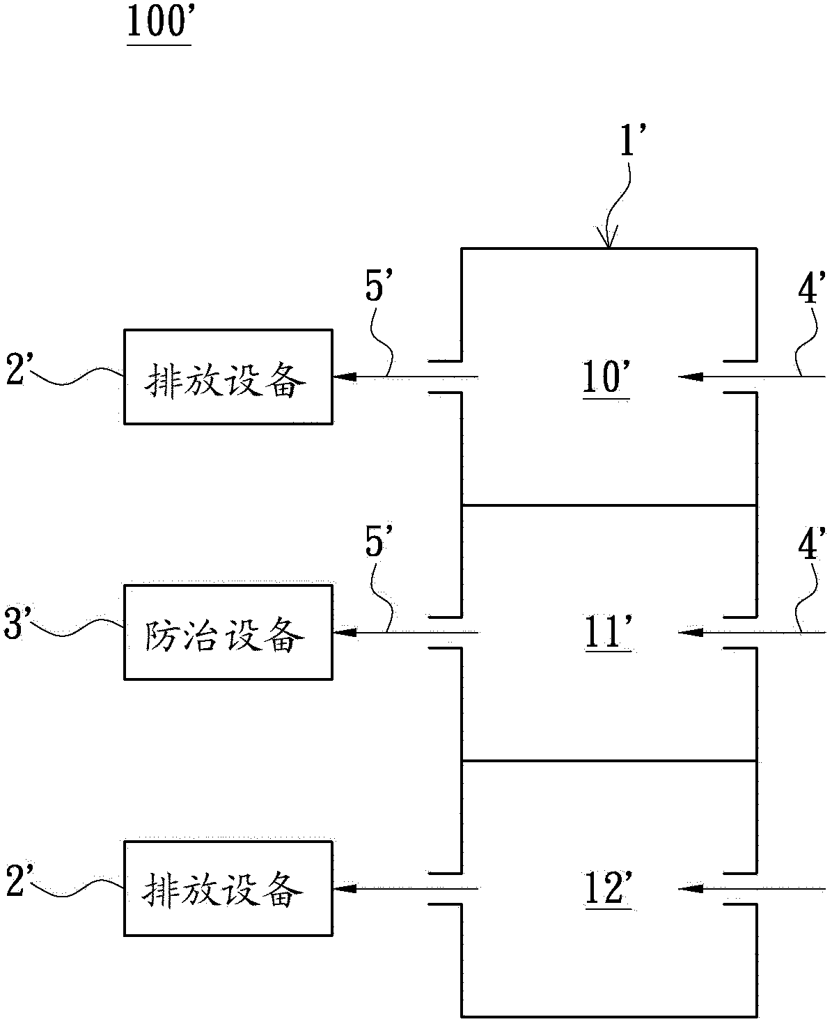
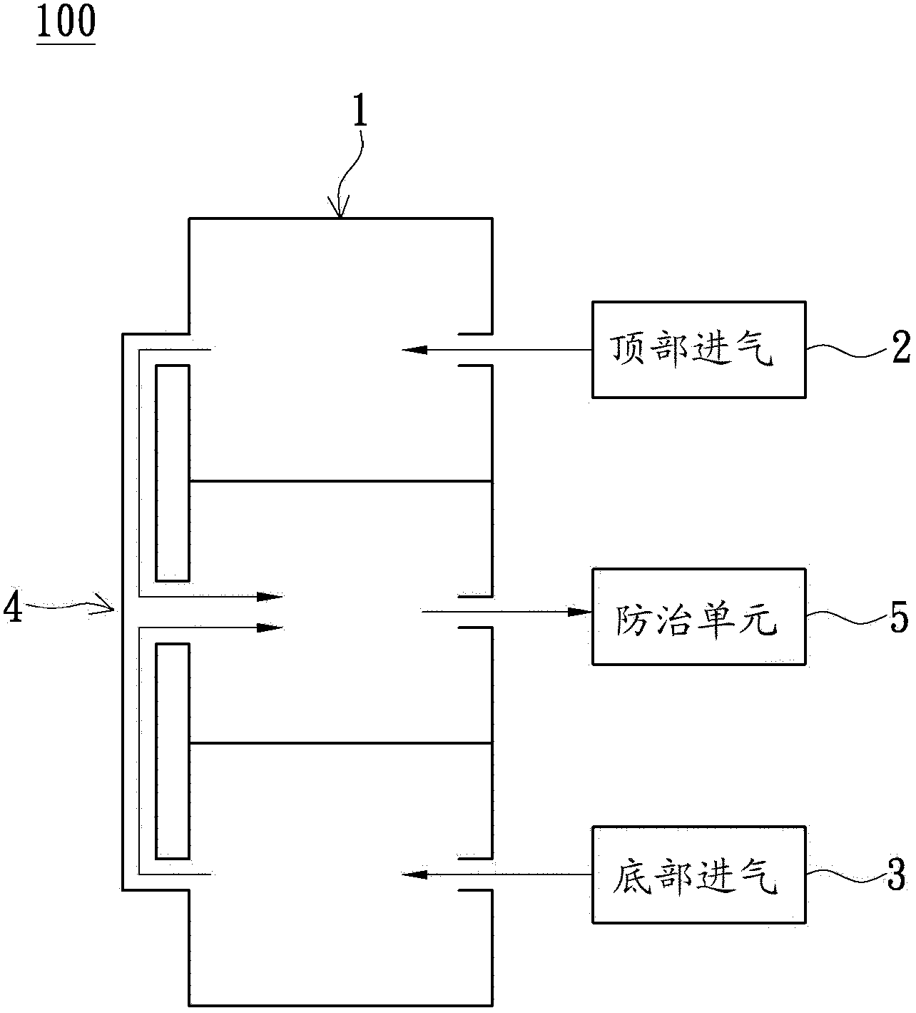
[0080] The present invention mainly provides a recovery system for volatile organic compounds, which can first introduce all gases (including VOCs) in the system into the heat treatment unit through the pipeline configuration of the system, and then discharge them into the prevention and control unit together, so as to improve the overall efficiency of the system. Equalization control efficiency. Hereinafter, specific structural features and recovery processes of the recovery system for volatile organic compounds will be described based on various drawings.

[0081] see figure 2 , is a schematic diagram of a recovery system for volatile organic compounds of the present invention, the recovery system 100 for volatile organic compounds includes a heat treatment unit 1, a top air intake unit 2, a bottom air intake unit 3, an air-inducing unit 4 and a control Unit 5. The heat treatment unit 1 includes an upper air chamber, an oven and a lower air chamber (not shown), the top ai...

no. 2 example

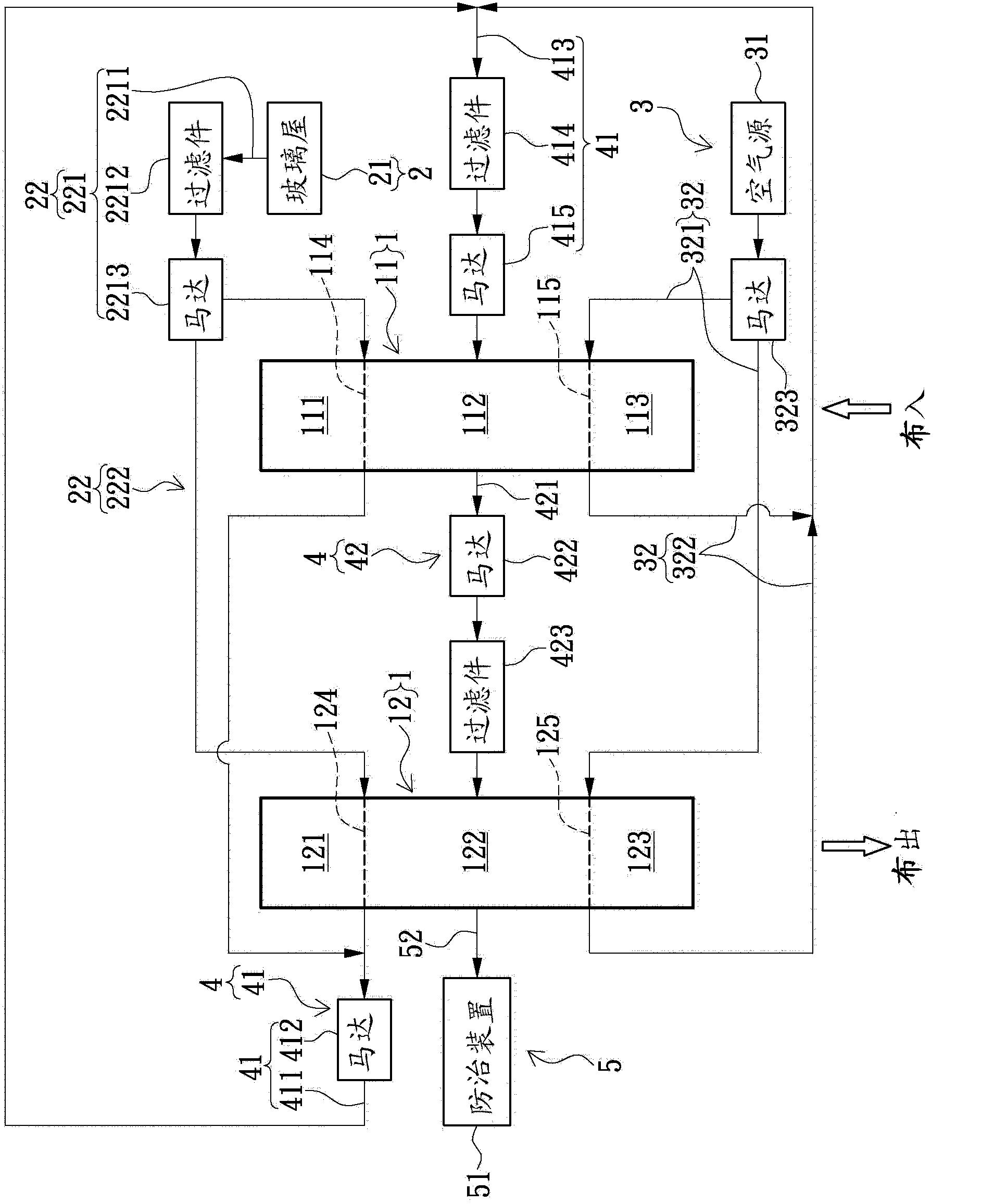
[0098] see Figure 5 , is a block diagram of a recovery system for volatile organic compounds in the second embodiment of the present invention. The difference between this embodiment and the previous embodiment is that the air outlet 322 of the air pipeline 32 of the bottom air intake unit 3 It is connected with the exhaust pipeline 52 of the control unit 5 .

no. 3 example

[0100] see Image 6 , is a block diagram of a recovery system for volatile organic compounds according to the third embodiment of the present invention. The introduction tube 2211 is connected and connected to the flow splitting portion 222 of the air guiding pipeline 22 through the first filter element 2212 and the first driving element 2213 .


PUM


Abstract

The invention relates to a volatile organic compound recovery system and a recovery process thereof. The volatile organic compound recovery system comprises a heat treatment unit, a top gas inlet unit, a gas guide unit and a prevention and control unit, wherein the heat treatment unit is provided with an upper gas chamber, an oven and a lower gas chamber, the top gas inlet unit is connected with the upper gas chamber, the gas guide unit is respectively connected with the upper gas chamber and the oven, and the prevention and control unit is connected with the oven, such that the VOCs discharged by the upper gas chamber of the heat treatment apparatus can be guided by the gas guide unit to enter the prevention and control unit so as to increase the homogenization control efficiency. The present invention further provides the recovery process of the volatile organic compound recovery system.

Description

technical field [0001] The invention relates to a treatment system for volatile organic compounds, in particular to a recovery system for volatile organic compounds and a recovery method thereof. Background technique [0002] By the way, among the sources of air pollution, in addition to the exhaust gas emitted by vehicles, the exhaust gas emitted by industries such as petrochemical industry, rubber industry, paint manufacturing industry, coating industry and semiconductor manufacturing industry, which has gradually flourished in recent years, will produce volatile Volatile organic compounds (Volatile organic compounds; VOCS) exhaust, thus causing serious pollution to air quality. [0003] Based on the harmfulness of VOCs, the Environmental Protection Agency has been collecting VOCs air pollution fees since 2006, and plans to increase the rate in 2010, which is estimated to increase from 12 yuan per kilogram to 25-30 yuan per kilogram. [0004] According to statistics in 20...

Claims


Application Information

Patent Timeline
IPC IPC(8): B01D53/74B01D53/00F23G7/06
Inventor 古鸿贤陈永福徐金传
Owner HONG TAI ELECTRIC IND
Learn More