Deflective roller friction pair lubricating oil film measurement experiment table

A technology of rollers and cylindrical rollers, applied in the field of experimental equipment for measuring the lubricating oil film of skewed roller friction pairs, can solve the problems of large left-right difference, large line speed difference, asymmetric load distribution, etc., and achieve increased reliability and operation The effect of convenience and simple structure

Inactive Publication Date: 2014-06-11
CHANGZHOU UNIV
View PDF6 Cites 17 Cited by
  • Summary
  • Abstract
  • Description
  • Claims
  • Application Information

AI Technical Summary

Problems solved by technology

[0006] ②Due to processing technology factors, the amount of modification at the two ends of the convex roller friction pair is not equal, resulting in asymmetrical convexity, and the error of a few microns at the two ends will cause the load distribution along the roller generatrix to be asymmetrical and have a large difference between the left and the right , the geometric gap of the original profile of the left and right film thickness is asymmetric
[0007] ③Due to factors such as installation errors, changes in the load loading position during actual work, radial clearance of the contact pair, and bending of the support shaft, the roller friction pair will inevitably produce a load offset, resulti

Method used


Image

  • Deflective roller friction pair lubricating oil film measurement experiment table
  • Deflective roller friction pair lubricating oil film measurement experiment table
  • Deflective roller friction pair lubricating oil film measurement experiment table

Examples


Embodiment Construction

[0025] In order to make the content, purpose, and technical solution of the present invention easier to understand clearly, the present invention will be further described in detail below with reference to the accompanying drawings and embodiments.

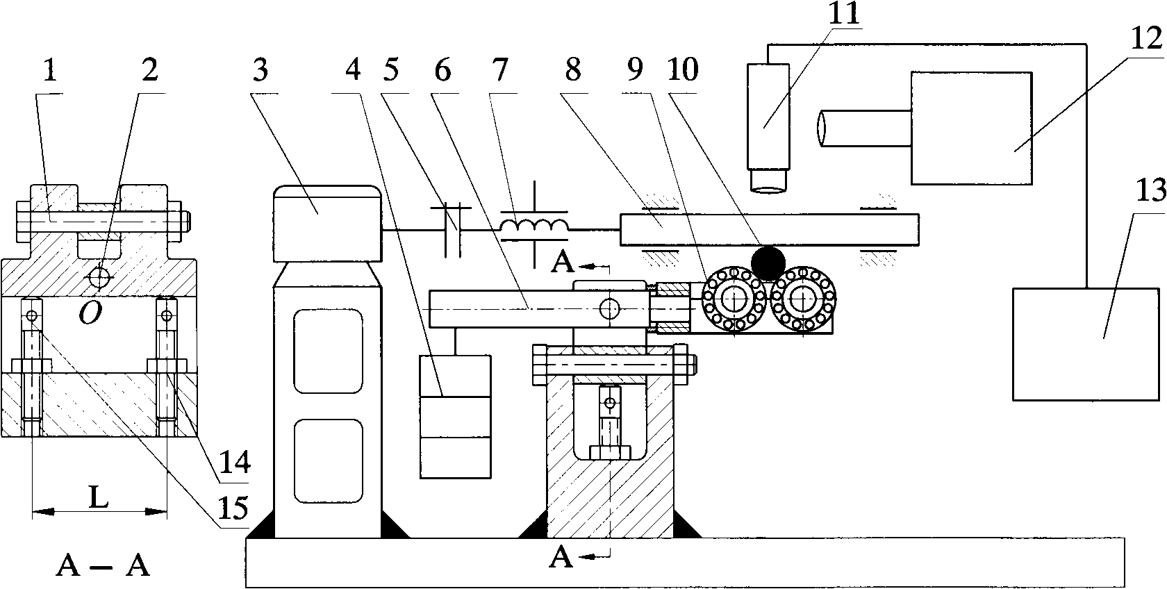
[0026] Such as figure 1 As shown, the servo motor 3 drives the sliding block 8 equipped with flat glass through the ball screw 7 to move linearly along the straight raceway, and the law of movement change is controlled by the servo motor 3. After the load 4 is loaded and amplified by the lever 6, the test roller 4 is supported by the roller bearing roller 9 to act on the flat glass, and the flat glass 8 drives the roller 10 of the test piece to rotate. Due to the heavy load, generally working above 1000N, the friction force generated between the test piece and the flat glass is sufficient to overcome the rolling friction of the supporting bearing roller and form pure rolling. The test roller 10 is supported by a rolling bearing 9. A ...


PUM


Abstract

The invention provides a deflective roller friction pair lubricating oil film measurement experiment table used for measuring pure rolling friction. According to the light interference principle, when a roller is in a deflective elastohydrodynamic working state, the thickness and shape of a line contact friction pair lubricating oil film are measured. The deflective roller friction pair lubricating oil film measurement experiment table has the following four advantages that a test piece is a cylindrical roller, and the deflection angle of a line contact pair in the axial direction of the roller can be accurately adjusted according to demands when the cylindrical roller makes contact with transparent materials; contact stress between the test roller and the transparent materials is in an elastohydrodynamic state, and the total load capacity is larger than or equal to 3000 N; the largest circular section of the cylindrical roller is stressed, and under the action of the force, elastic deformation of the roller exceeds deflection amount of the roller; the test roller is supported by a bearing idler wheel, and rolls purely along the largest circular section of the test roller. The deflective roller friction pair lubricating oil film measurement experiment table is simple in structure, high in practicability and reliable in measurement of the thickness and shape of the deflective cylindrical roller friction pair lubricating oil film in rolling friction, and axial deflection amount of the line contact friction pair can be determined accurately and easily.

Description

Technical field [0001] The invention relates to the technical field of measuring the thickness and shape of the elastohydrodynamic lubricating oil film of a roller friction pair in a skewed state, in particular to an experimental device for measuring the lubricating oil film of a skewed roller friction pair. Background technique [0002] With the rapid development of the national economy and the aggravation of the crisis of energy shortage, mechanical equipment has gradually developed in the direction of high speed and heavy load, and the technical requirements of the green economy have been continuously improved. As the key moving parts that determine the dynamic performance of various mechanical equipment, rollers The importance of friction pair design and lubrication technology has become increasingly prominent. This can be seen from the current high-speed passenger car bearings, precision machine tool spindle bearings, tunnel shield machine spindle bearings and assembling mach...

Claims


Application Information

Patent Timeline
IPC IPC(8): G01B11/06G01B11/24
Inventor 王艳飞薛宇华同曙丁建宁坎标苗乃明李晓艳
Owner CHANGZHOU UNIV
Why Eureka
Try Eureka