
Reference voltage generator and corresponding integrated circuit

A reference voltage and generator technology, applied in instruments, regulating electrical variables, control/regulating systems, etc., can solve the problems of the normal use of high-voltage and low-power integrated circuits, the adverse effects of normal use, and the large current variation range. The effect of low power consumption

Inactive Publication Date: 2014-06-11
IWATT INTEGRATED CIRCUITS TECHNOLOGY (TIANJIN) LIMITED
View PDF5 Cites 2 Cited by
  • Summary
  • Abstract
  • Description
  • Claims
  • Application Information

AI Technical Summary

Problems solved by technology

The above-mentioned input voltage between 7V and 18V is only an example. The current high-voltage process can make the input voltage as high as 100V, so that the ratio of the maximum current Imax to the minimum breakdown current Imin in the reference voltage generator may be much greater than the above 12 times. As a result, it has a serious adverse effect on the normal use of high-voltage and low-power integrated circuits
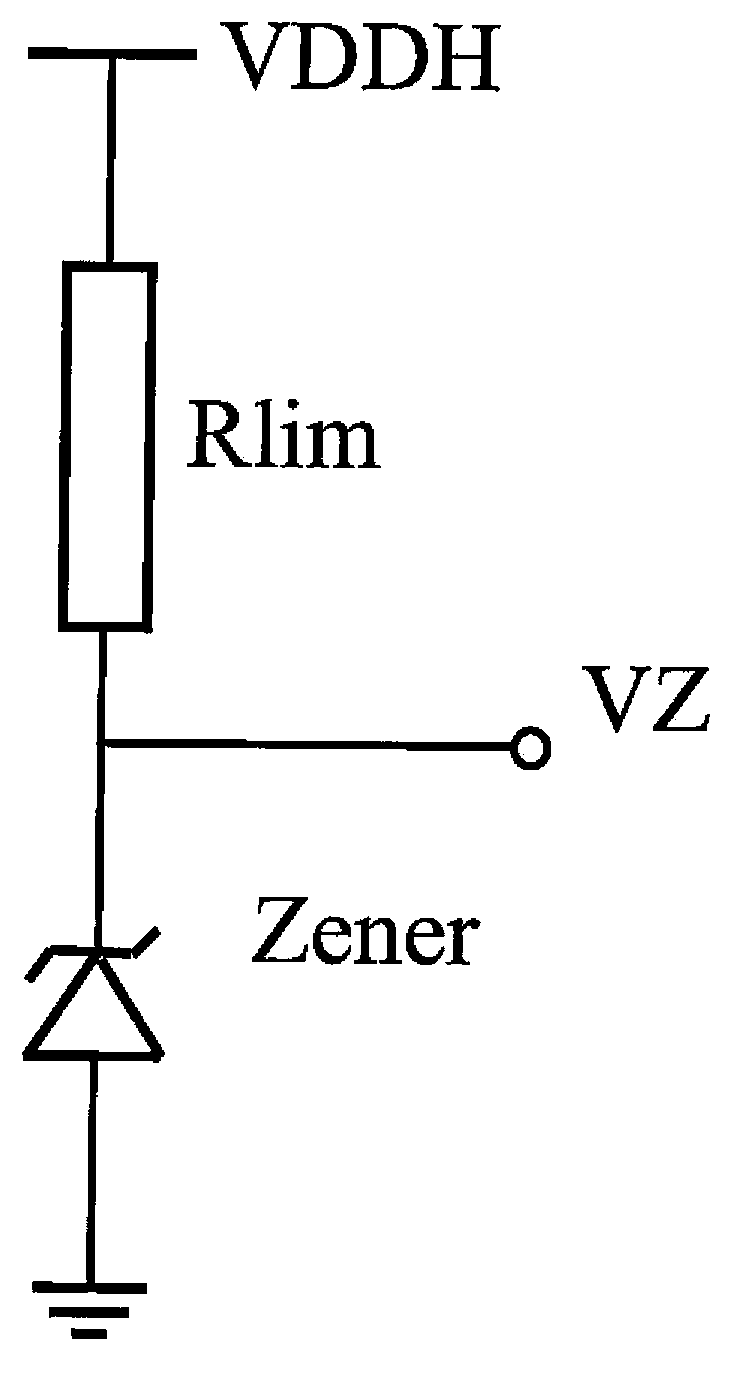
[0009] It can be seen that the traditional reference voltage generator has the disadvantage that the current variation range in the reference voltage generator is too large when the input voltage changes greatly

Method used


Image

  • Reference voltage generator and corresponding integrated circuit
  • Reference voltage generator and corresponding integrated circuit

Examples


Embodiment Construction

[0024] Various exemplary embodiments of the present invention are described in detail below with reference to the accompanying drawings. It should be noted that alternative embodiments of the structures and methods disclosed herein can be readily recognized from the following description and used as possible embodiments that may be employed without departing from the principles and spirit of the invention.

[0025] It should be understood that these exemplary embodiments are given only to enable those skilled in the art to better understand and implement the present invention, but not to limit the scope of the present invention in any way.

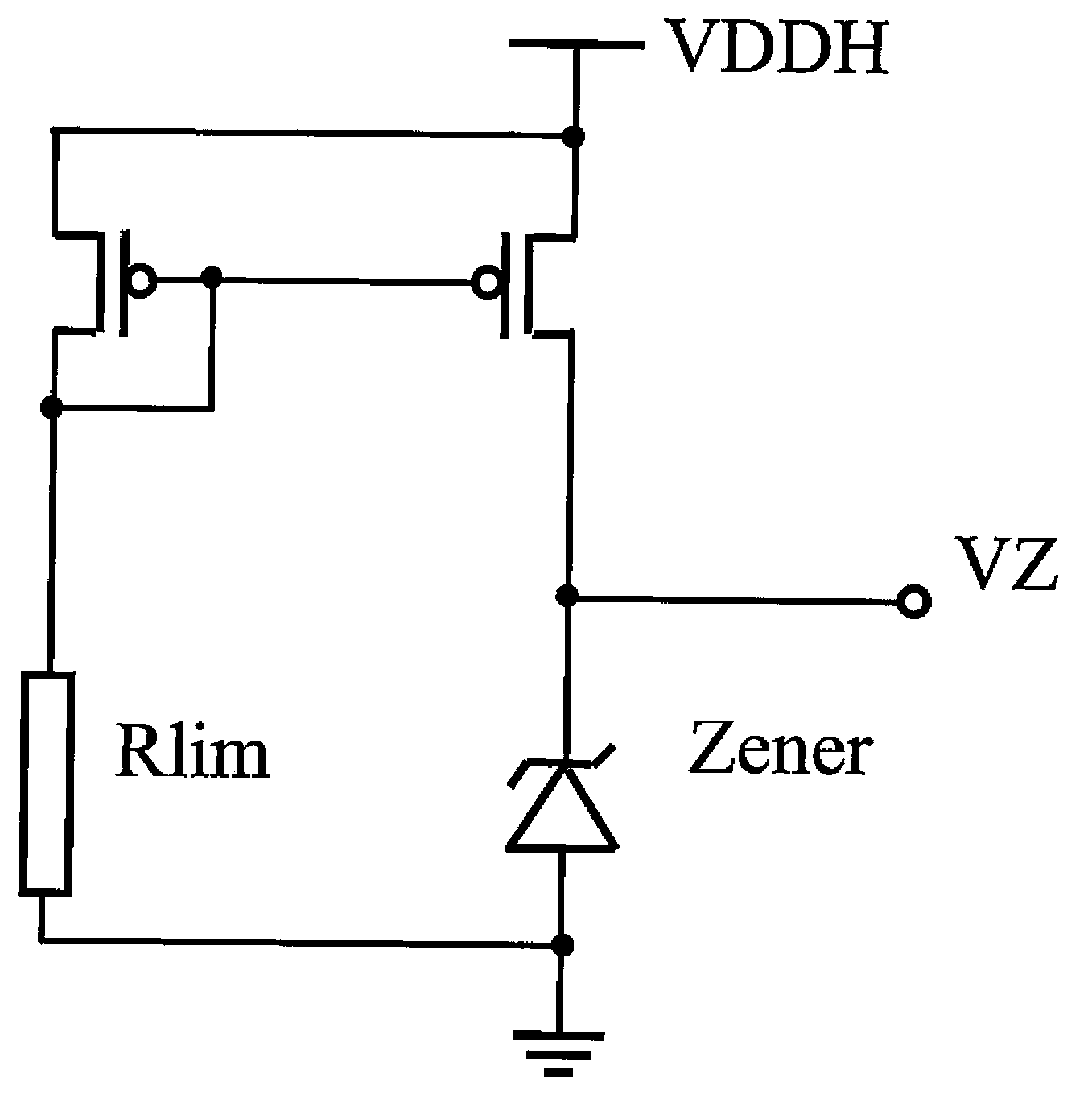
[0026] refer to figure 2 , which is a circuit diagram of a reference voltage generator for a high voltage low power consumption integrated circuit according to an exemplary embodiment of the present invention.

[0027] Such as figure 2 As shown in , the reference voltage generator according to the present invention includes two left an...


PUM


Abstract

The invention provides a reference voltage generator and a corresponding integrated circuit. The reference voltage generator comprises a current mirror, a resistive element and a voltage-stabilizing element, wherein the current mirror is connected between an input voltage and the ground and comprises a source current branch circuit and a mirror image current branch circuit; the resistive element is connected into the source current branch circuit in series; the voltage-stabilizing element is connected into the mirror image current branch circuit in series, mirror image current generated in the mirror image current branch circuit can be operated so as to meet the requirement on working current of the voltage-stabilizing element, and one end of the voltage-stabilizing element is used as a reference voltage output end. According to an implementation mode of the invention, current in a smaller change range and lower power consumption are provided for the application of the input voltage in a larger change range, thus the operating of a high-voltage lower-power-consumption integrated circuit can be facilitated, and the reference voltage generator particularly has the advantage in the application needing smaller current during standby.

Description

technical field [0001] Embodiments of the present invention relate generally to complementary metal oxide semiconductor (CMOS) high voltage low power integrated circuits, and more particularly to reference voltage generators and corresponding integrated circuits for high voltage low power integrated circuits. Background technique [0002] A reference voltage generator is the basic block used to generate a coarse reference voltage in high voltage integrated circuits. Such as figure 1 As shown in , the structure of the traditional reference voltage generator is to use a zener tube (zener) in series with a current limiting resistor (Rlim) to generate a reference voltage (VZ), where the power supply voltage (VDDH) is the input voltage. [0003] However, in figure 1 In the reference voltage generator shown in , it is very difficult to achieve low power consumption as the input voltage increases. Moreover, when the input voltage changes, the current in the reference voltage gen...

Claims


Application Information

Patent Timeline
Patent Type & Authority Applications(China)
IPC IPC(8): G05F3/26
CPCG05F3/185
Inventor 宋振宇孙俊岳
Owner IWATT INTEGRATED CIRCUITS TECHNOLOGY (TIANJIN) LIMITED
Learn More