Self rectification/guiding power stable switching circuit

A technology of power supply stabilization and conversion circuit, applied in the direction of output power conversion devices, electrical components, etc., can solve the problems of low efficiency, high power consumption, poor reliability, etc., and achieve the effect of low cost, low power consumption, and high power factor

Inactive Publication Date: 2014-06-11
XIAN ZHIHAI POWER TECH
View PDF0 Cites 1 Cited by
  • Summary
  • Abstract
  • Description
  • Claims
  • Application Information

AI Technical Summary

Problems solved by technology

[0008] The invention provides a self-rectifying / guiding power supply stable conversion circuit, which mainly solves the problems of high power consumption, low efficiency and poor reliability of existing low-voltage new energy power converters

Method used


Image

  • Self rectification/guiding power stable switching circuit
  • Self rectification/guiding power stable switching circuit
  • Self rectification/guiding power stable switching circuit

Examples


Embodiment Construction

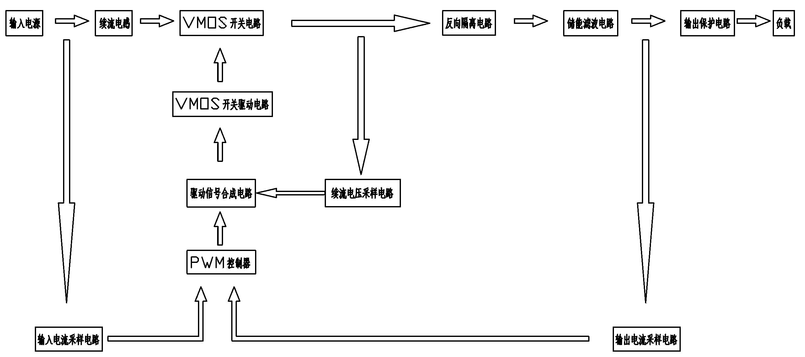
[0022] The self-rectifying / guiding power supply stabilization conversion circuit includes a VMOS switch circuit and a width-adjustable pulse control circuit. The isolation circuit and the energy storage filter circuit are connected to the load, the input end of the VMOS switch circuit is also connected to the output end of the VMOS switch drive circuit, and the output end of the width-adjustable pulse control circuit is driven by the drive signal synthesis circuit and the VMOS switch The input end of the circuit is connected, the input end of the width-adjustable pulse control circuit is connected with the output end of the input power supply through the input current sampling circuit, and the input end of the driving signal synthesis circuit is also connected with the output end of the VMOS switch circuit through the freewheeling voltage sampling circuit The input end of the width-adjustable pulse control circuit is also connected with the output end of the energy storage filt...


PUM


Abstract

The invention provides a self rectification / guiding power stable switching circuit. An L1, a D3 and a C14 form an LDC of a BOOST circuit, in order to adapt to the asymmetry of an input power supply, such as unipolar direct current, unipolar square waves and unipolar triangular waves, the L1 adopts a differential mode symmetric style, and an inductor can also be arranged only at the positive end or negative end of an input loop to serve as the L1. The BOOST circuit can automatically achieve automatic identification orientation of a bipolar power supply (alternating current sine waves, square waves, triangular waves, alternating current power frequency, medium frequency, low frequency and ultra-low frequency), and automatic identification orientation of a unipolar power supply (direct current, direct current square waves, direct current triangular waves and the like), and the alternating current bipolar power supply and the direct current unipolar power supply can be freely connected regardless of the positive pole and the negative pole. The self rectification / guiding power stable switching circuit solves the problems that an existing low-voltage new energy power supply converter is high in power consumption, low in efficiency and poor in reliability.

Description

technical field [0001] The invention relates to a power conversion circuit. Background technique [0002] In recent years, photovoltaic power generation, wind power generation, battery power supply and other renewable new energy systems with AC low voltage and DC low voltage power supply have been widely used. It is imperative to improve the power supply efficiency, power supply quality and power supply reliability of low voltage new energy power supply systems. [0003] At present, the power conversion known in the art basically adopts: [0004] 1. AC (AC) input, using a full-wave rectifier to rectify the input AC (AC) power to DC (DC) power, and then convert DC / DC to DC (DC) output. This kind of scheme solves the conversion problem of higher input voltage AC power supply and low-power power supply. However, when low-voltage AC power input and high-power power conversion, because the voltage drop of the AC / DC rectifier circuit is relatively high, high power consumption is...

Claims


Application Information

Patent Timeline
Patent Type & Authority Applications(China)
IPC IPC(8): H02M1/088H02M1/32
Inventor 胡家培胡民海
Owner XIAN ZHIHAI POWER TECH
Why Eureka
Try Eureka