Gallery type road wind and light energy combined power station

A technology of wind energy and promenade, which is applied in the field of promenade road wind energy composite power station, can solve the problems of high power generation cost, difficulty in grid connection, cost pressure, etc., reduce redundant construction and investment, shorten construction complexity, The effect of making up for defects and waste

Active Publication Date: 2014-06-11
郑东武
View PDF6 Cites 5 Cited by
  • Summary
  • Abstract
  • Description
  • Claims
  • Application Information

AI Technical Summary

Problems solved by technology

Although solar energy and wind energy have the advantages of being clean, safe, extensive, sufficient, and maintenance-free, and have great potential for development, there are also some obstacles that need to be overcome urgently in the development of solar energy and wind energy. One of them is that the energy distribution density is small, and development often It needs to occupy a huge area, and the land acquisition will bring great cost pressure to the construction of the power station, especially in the economically developed areas along the southeast coast
However, the construction of centralized solar power stations and wind farms in the central and western regions where the land acquisition pressure is relatively relaxed will face difficulties such as difficulty in grid connection, high cost of long-distance transmission, and large losses.
Distributed wind farms and photovoltaic power stations built nearby also have problems of small scale and redundant construction of supporting facilities, resulting in huge investment and high power generation costs

Method used


Image

  • Gallery type road wind and light energy combined power station
  • Gallery type road wind and light energy combined power station
  • Gallery type road wind and light energy combined power station

Examples


Embodiment Construction

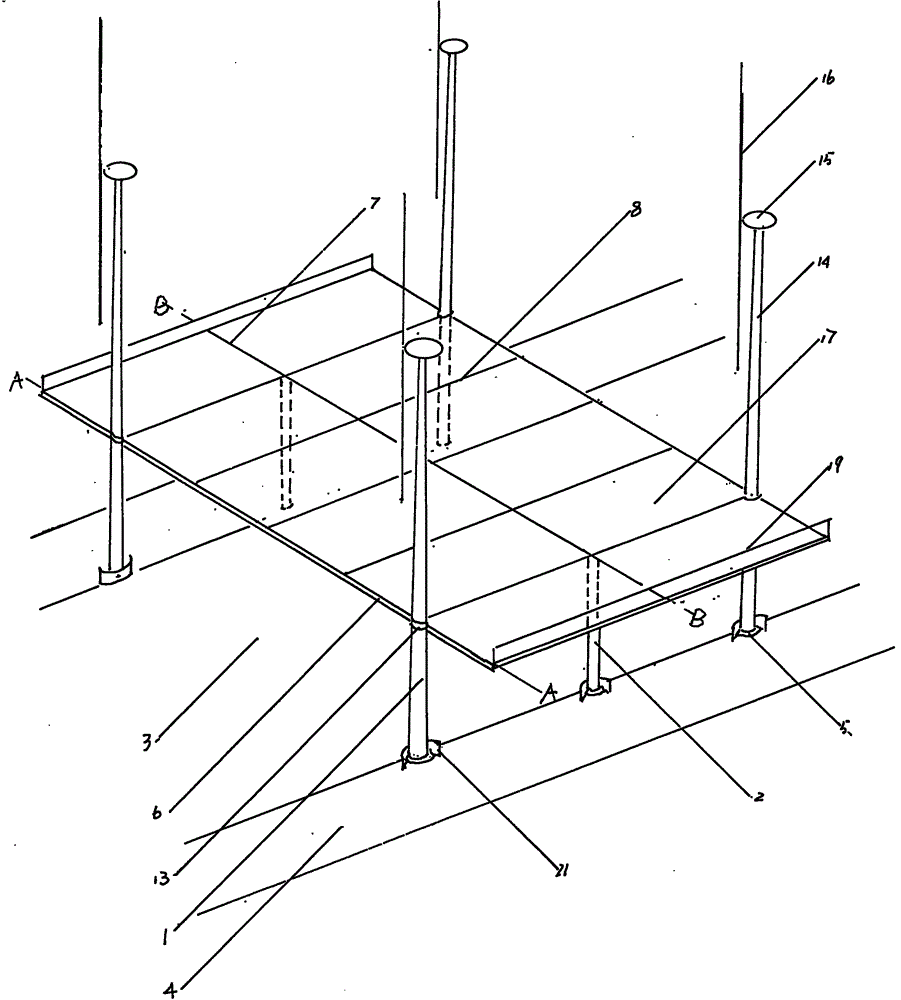
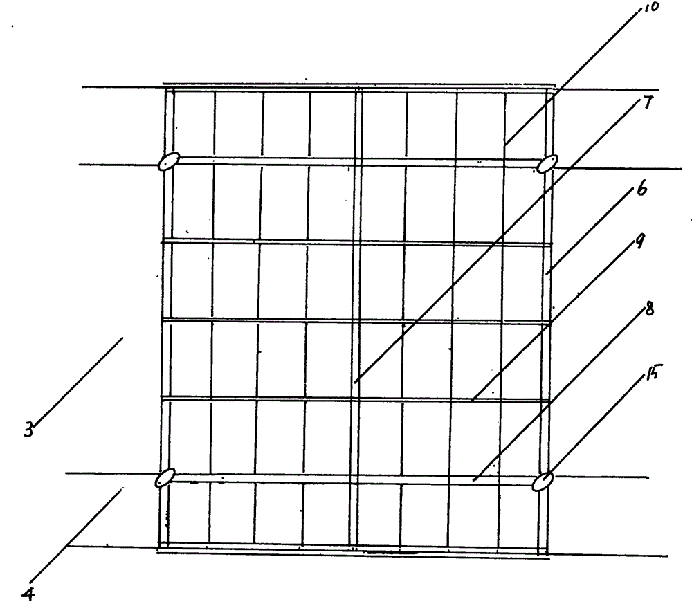
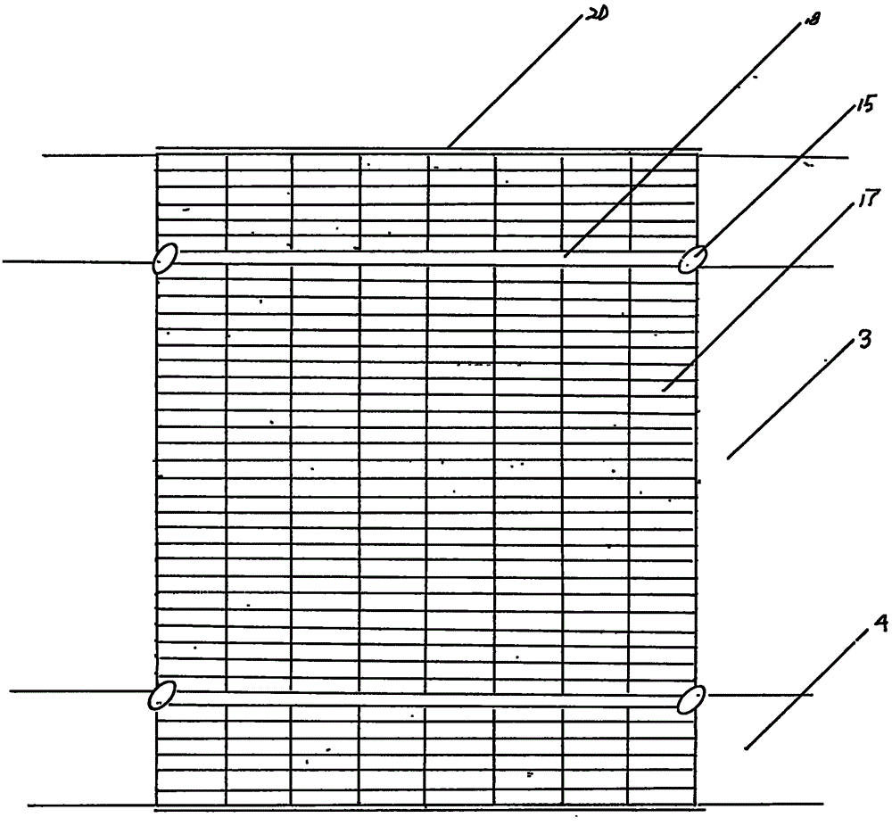
[0029] figure 1 , 2 , 3, 4, 5, 6, show the specific implementation method of the present invention, its external dimensions are about high * wide * long be 7 * 30 * 20 meters, only the promenade type road scenery that construction length can not limit A section of a composite power station; its structural features include a steel frame platform, a wind turbine, a solar photovoltaic module array, and a matching current control box. 2. Set up and fix on the concrete foundation and steel embedded parts 5 on the sidewalks 4 on both sides of the roadway 3 in turn to form a steel frame platform foundation support structure. The main support column (fan lower tower) 1 connected to the two sides of the road is connected to the outer flange 13 by the main cross-beam 6 across the top of the roadway 3, and the auxiliary cross-beam 7 is across the top of the roadway 3 On the auxiliary support column 2 connecting the two sides of the road, the adjacent main column (fan lower tower) 1 and...


PUM


Abstract

The invention relates to a gallery type road wind and light energy combined power station and belongs to the field of new energy development and application. A novel method for building a centralized wind and light energy power station is invented. The capability of bearing and spanning ground constructed objects of steel frame platforms is mainly utilized, a solar photovoltaic power station and a wind power plant are built on the steel frame platforms, and therefore the purpose of fully utilizing idle and abundant solar energy and wind energy of ground permanent constructed objects such as roads to generate power is achieved. The gallery type road wind and light energy combined power station is characterized in that a wind driven generator tower serves as a main support, girder pipe columns are used for assisting, and therefore the steel frame platforms are formed through combination and fixation; multiple adjacent steel frame platforms commonly form a gallery-shaped steel frame platform body which is provided with a solar photovoltaic assembly array, and the tower is provided with a small and medium size wind driven generator; a current control cabinet formed by integrating devices such as a confluence controller and an inverter can also be installed on the steel frame platform body. Electric power generated by the power station can be provided for a grid or adjacent loads, and meanwhile, the function of protecting the road and the traffic safety can be achieved.

Description

technical field [0001] The invention belongs to the field of new energy development and application. It has invented a new method for jointly designing and constructing wind farms and solar photovoltaic power stations. It is especially suitable for the three-dimensional development and comprehensive utilization of fixed ground structures such as roads, railways, and parking lots. Large-scale centralized development of solar energy and wind energy in areas with abundant solar energy and wind energy has invented a promenade-style road-wind energy composite power station. Background technique [0002] The depletion of fossil energy and the deteriorating environment have become important bottlenecks restricting my country's economic and social development. While the energy security situation is not optimistic, my country's environmental pollution is also worrisome. The total discharge of various major pollutants is approaching the carrying limit of the environment, especially th...

Claims


Application Information

Patent Timeline
Patent Type & Authority Applications(China)
IPC IPC(8): H02S10/12H02S20/10
CPCF03D9/007F03D9/255F05B2240/9113H02S10/12Y02B10/30Y02E10/50Y02E10/72Y02E10/728
Inventor 郑东武
Owner 郑东武
Why Eureka
Try Eureka