Vibration element and electronic device
A vibrator and electrode technology, applied in the field of vibrator and electronic equipment, can solve the problem of upper electrode sticking to the lower electrode, etc.
- Summary
- Abstract
- Description
- Claims
- Application Information
AI Technical Summary
Problems solved by technology
Method used
Image
Examples
Embodiment approach 1
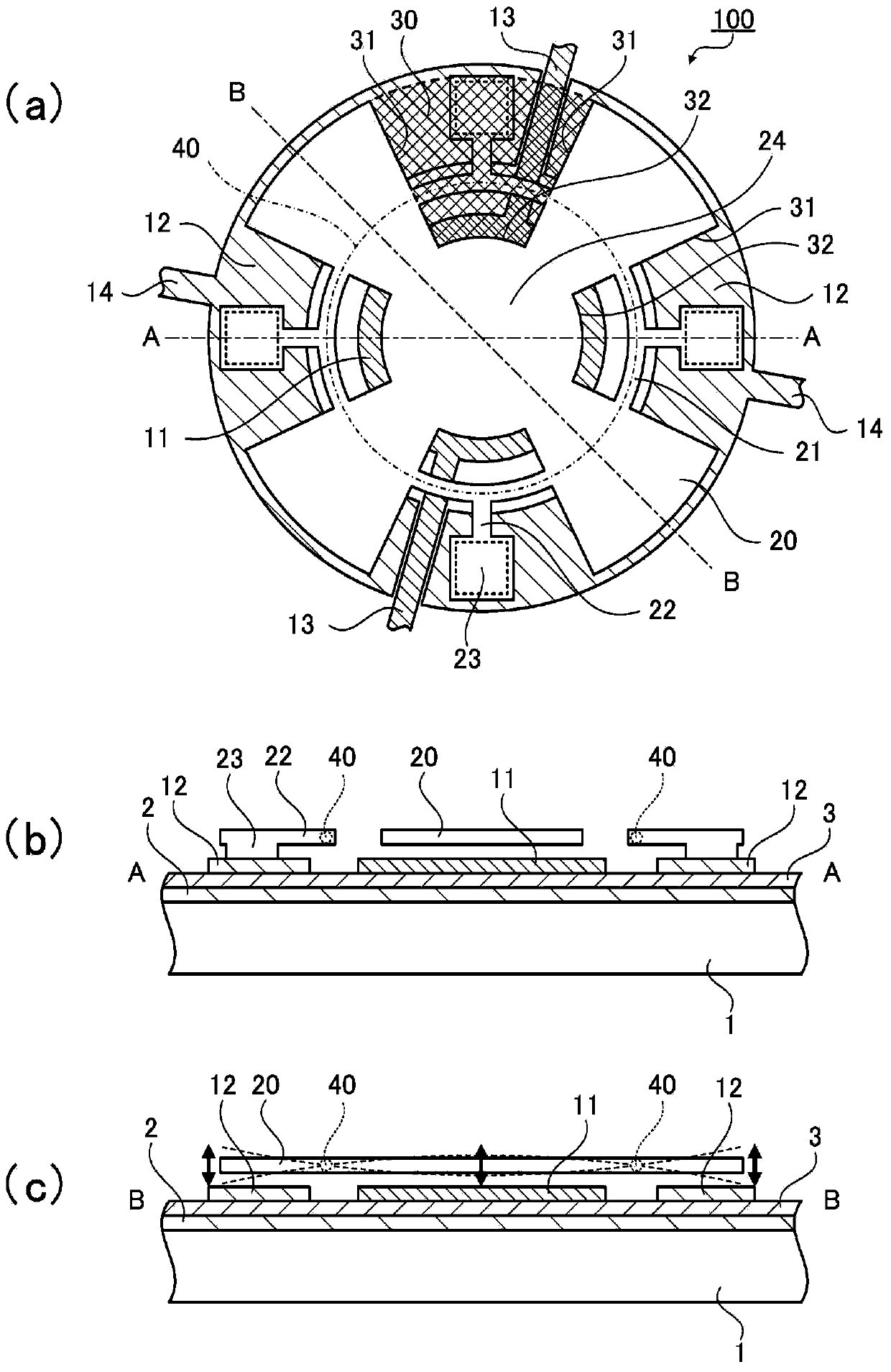
[0050] First, the MEMS vibrator 100 as the vibrator of Embodiment 1 will be described.
[0051] figure 1 (a) is a top view of the MEMS vibrator 100, figure 1 (b) is figure 1 (a) A-A sectional view, figure 1 (c) is figure 1 (a) BB sectional view.
[0052] The MEMS vibrator 100 is a MEMS vibrator provided with a movable upper electrode (vibrator) formed away from the substrate by etching a sacrificial layer laminated on the main surface of the substrate.
[0053] In addition, the term "sacrifice layer" refers to a layer temporarily formed of an oxide film or the like, and is removed by etching after desired layers are formed above, below, and around the sacrificial layer. By removing the sacrificial layer, desired gaps or cavities are formed between upper, lower and surrounding layers, and desired structures are formed separately.
[0054] The MEMS vibrator 100 includes a substrate 1 , a first lower electrode 11 , a second lower electrode 12 , an upper electrode 20 as a vi...
Embodiment approach 2
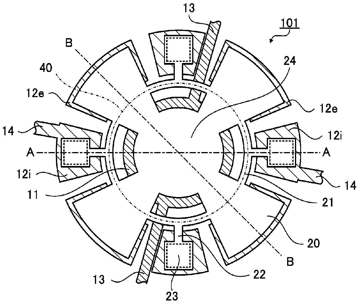
[0094] Next, the MEMS vibrator 101 as the vibrator of Embodiment 2 will be described. In addition, in the description, the same reference numerals are used for the same structural parts as those of the above-mentioned embodiment, and repeated descriptions are omitted.
[0095] image 3 is a plan view of the MEMS vibrator 101 .
[0096] The MEMS vibrator 101 is configured to include a substrate 1, a first lower electrode 11, a second lower electrode 12e, an upper electrode 20 as a vibrating body, a support portion composed of a connecting beam 21 and a supporting beam 22, a fixed portion 23, and a fixed base portion 12i. Wait.
[0097] Such as figure 1 As shown in (a), in the first embodiment (MEMS vibrator 100 ), the structure in which the upper electrode 20 is electrically connected to the second lower electrode 12 via the connection beam 21 , the support beam 22 and the fixing portion 23 has been described, but in this embodiment Among them, the part constituting the sec...
Deformed example 1
[0115] Figure 6 (a) to (c) are plan views showing modifications of the lower electrode as the MEMS vibrator of the first modification.
[0116] In Embodiment 1, such as figure 1 As shown in (a), the structure in which the lower electrode includes both the first lower electrode 11 and the second lower electrode 12 has been described, but the structure is not limited to this, and the lower electrode may have a structure of only one lower electrode.
[0117] Figure 6 The modified example shown in (a) is an example in which only the first lower electrode 11 constitutes the lower electrode.
[0118] Figure 6 The modified example shown in (b) is an example in which only the second lower electrode 12 constitutes the lower electrode.
[0119] Figure 6 The modified example shown in (c) is an example in which the lower electrode is constituted only by the second lower electrode 12e.
[0120] In such a configuration, although the vibration energy is different, it is possible to...
PUM
 Abstract
Description
Claims
Application Information
 - R&D
- Intellectual Property
- Life Sciences
- Materials
- Tech Scout
- Unparalleled Data Quality
- Higher Quality Content
- 60% Fewer Hallucinations
Browse by: Latest US Patents, China's latest patents, Technical Efficacy Thesaurus, Application Domain, Technology Topic, Popular Technical Reports.
© 2025 PatSnap. All rights reserved.Legal|Privacy policy|Modern Slavery Act Transparency Statement|Sitemap|About US| Contact US: help@patsnap.com


