
Chassis and method for producing chassis

A manufacturing method and technology for a bottom plate, which are applied to chemical instruments and methods, manufacturing tools, circuit layout on conductive chassis, etc., can solve the problems of increasing the number of components and increasing the thickness of portable devices, and achieve the effect of suppressing damage.

Active Publication Date: 2014-06-11
PROTERIAL LTD
View PDF8 Cites 14 Cited by
  • Summary
  • Abstract
  • Description
  • Claims
  • Application Information

AI Technical Summary

Problems solved by technology

However, there are problems such as an increase in the number of parts and an increase in the thickness of portable devices due to the additional graphite sheet, etc., and it is required to improve the heat dissipation performance of the bottom plate itself

Method used


Image

  • Chassis and method for producing chassis
  • Chassis and method for producing chassis
  • Chassis and method for producing chassis

Examples


Embodiment )

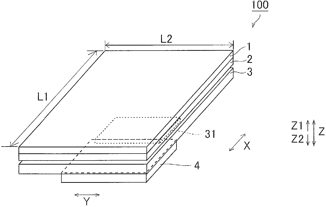
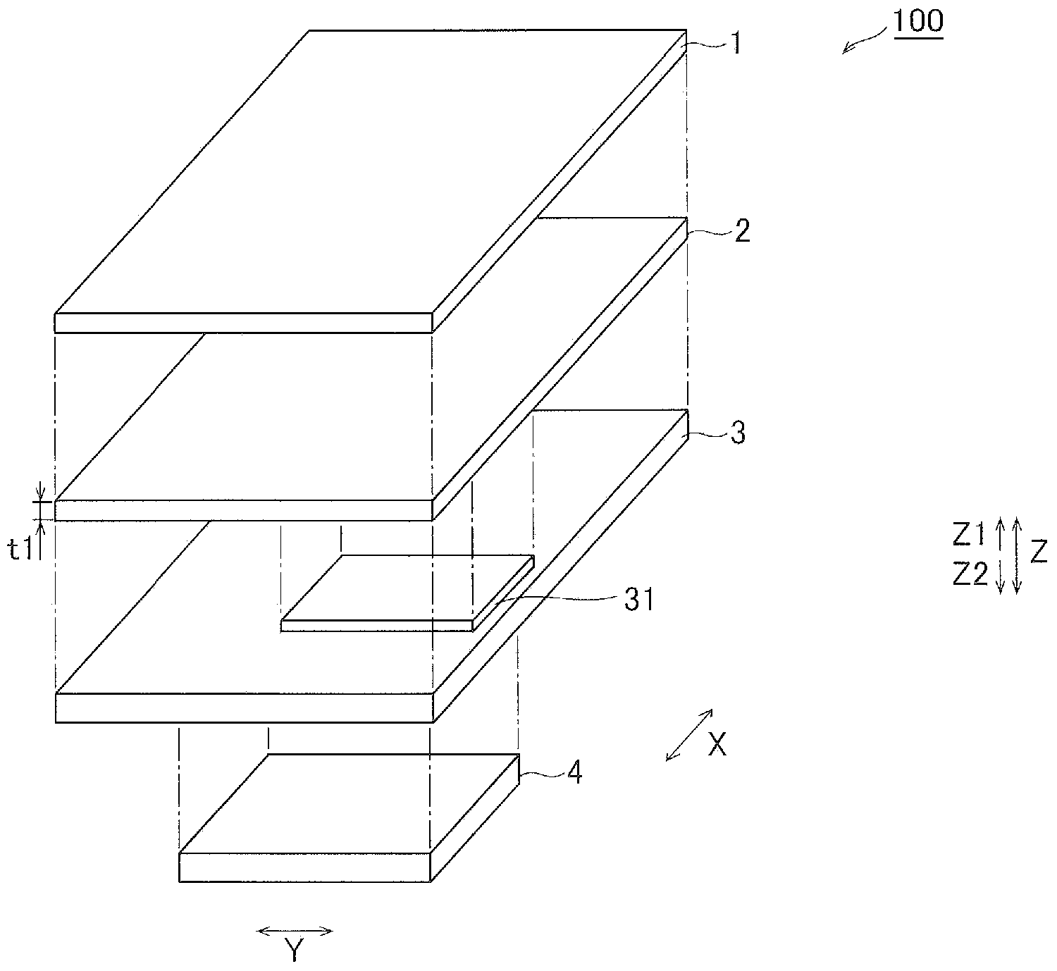
[0086] Next, refer to figure 2 , image 3 , Figure 5 ~ Figure 10 Describes the measurement of heat dissipation performance and the measurement of mechanical strength to confirm the effects of the present invention. However, unless otherwise specified, "thickness" and "plate thickness" mean average values.

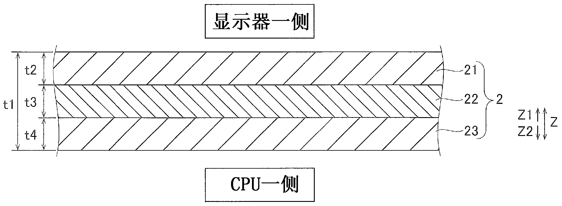
[0087] In this embodiment, use image 3 The bottom plate 2 of the above embodiment is shown. Specifically, Examples 1 to 8 (reference Figure 7 ) A base plate 2 made of a composite material obtained by stacking the SUS layer 21 formed of SUS304, the Cu layer 22 formed of Cu, and the SUS layer 23 formed of SUS304 in this order. In addition, Examples 9 to 13 (reference Figure 8 ) A base plate 2 made of a composite material obtained by stacking the SUS layer 21 formed of SUS301, the Cu layer 22 formed of Cu, and the SUS layer 23 formed of SUS301 in this order.

[0088] In addition, in Examples 1 to 13, the thickness t1 (=t2+t3+t4, total thickness) of the bottom plate 2 was 0.3 ...


PUM

PropertyMeasurementUnit
directional tensile yield strengthaaaaaaaaaa

Abstract

This chassis (2) comprises a clad material obtained by roll bonding a first layer (21), which is formed from an austenitic stainless steel, a second layer (22), which is formed from Cu or a Cu alloy and which is laminated on the first layer, and a third layer (23), which is formed from an austenitic stainless steel and which is laminated on that side of the second layer which is opposite the first layer, wherein the thickness of the second layer is 15% or more of the thickness of the clad material.

Description

Technical field [0001] The present invention relates to a chassis suitable for use in portable devices with built-in electronic components accompanied by heat dissipation, and a method for manufacturing the chassis, and more particularly to a chassis using stainless steel and Cu, and a method for manufacturing the chassis. Background technique [0002] In the past, in portable devices and the like, in order to protect the display portion for displaying images from external impact, a base plate made of stainless steel with high mechanical strength has been used. For example, Japanese Patent Application Laid-Open No. 2006-113589 discloses a display device including a panel unit and a bottom plate for fixing and supporting the panel unit. In addition, although there is no clear description in Japanese Patent Application Laid-Open No. 2006-113589, it can be considered that the bottom plate of the display device is formed of stainless steel having a thickness of about 0.3 mm to about ...

Claims


Application Information

Patent Timeline
Patent Type & Authority Applications(China)
IPC IPC(8): H05K7/04H01L23/373H05K7/20
CPCH05K7/20H01L2924/0002H01L23/3735H01L23/3736H05K7/04B32B15/015B23K20/02B23K20/04B23K20/227B23K2103/22B32B15/04B32B15/043B32B15/18B32B15/20C21D1/26C21D9/0068C21D2211/001C21D2251/00C21D2251/02C22C38/16C22C38/18H05K5/0213Y10T428/12722Y10T428/12903Y10T428/1291Y10T428/12917Y10T428/12924Y10T428/12958Y10T428/12979Y10T428/2495H01L2924/00
Inventor 织田喜光渡边启太石尾雅昭
Owner PROTERIAL LTD
Learn More