Electrode pin welding ring pressing device and method

A technology of electrode pins and welding rings, applied in auxiliary devices, manufacturing tools, welding equipment, etc., can solve problems such as no unified operation process, achieve the effect of ensuring consistency and improving product quality

Active Publication Date: 2016-04-27
XIAN YONGDIAN ELECTRIC
View PDF4 Cites 0 Cited by
  • Summary
  • Abstract
  • Description
  • Claims
  • Application Information

AI Technical Summary

Problems solved by technology

[0005] At present, the market does not have a unified operation process for the pressing method of the welding ring of the electrode pin

Method used


Image

  • Electrode pin welding ring pressing device and method
  • Electrode pin welding ring pressing device and method
  • Electrode pin welding ring pressing device and method

Examples


Embodiment Construction

[0022] Hereinafter, the present invention will be described in detail with reference to the drawings and examples. It should be noted that, in the case of no conflict, the embodiments in the present application and the features in the embodiments can be combined with each other.

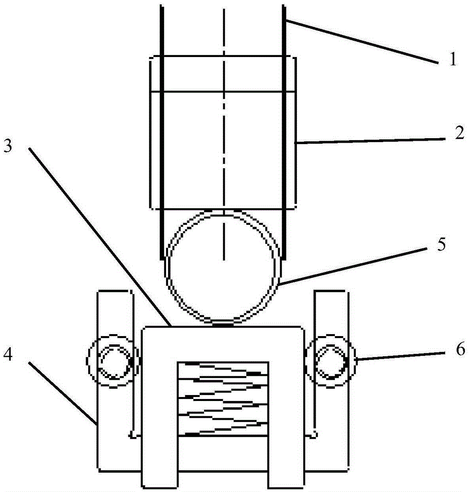
[0023] figure 1 It is a schematic diagram of the overall structure of the welding ring pressing device for electrode pins provided by the preferred embodiment of the present invention. Such as figure 1 As shown, the electrode pin welding ring pressing device provided by the preferred embodiment of the present invention includes a welding ring pick-up device 1, an extrusion module 2, a spring table 3 and a groove 4, and the welding ring pick-up device 1 is partially sleeved on the extrusion In the pressing module 2 , the pressing module 2 is used to press the welding ring 5 placed on the spring table 3 , and the spring table 3 is located in the groove 4 . The two side walls of the groove 4 each inc...


PUM


Abstract

The invention provides a device and a method of pressing a welding ring of an electrode pin. The device comprises a welding ring pickup device 1, an extrusion module 2, a spring table 3 and a groove 4, wherein the welding ring pickup device 1 is partially sleeved in the extrusion module 2, the extrusion module 2 is used for extruding the welding ring 5 positioned on the spring table 3, and the spring table 3 is arranged in the groove 4. Each of two sidewalls of the groove 4 comprises a roller 6 for shaping the edge of the extruded welding ring 5.

Description

technical field [0001] The invention belongs to the field of electrode packaging, and in particular relates to a pressing device and method for welding rings of electrode pins. Background technique [0002] IGBT (Insulated Gate Bipolar Transistor) is a new type of power device, which combines the dual advantages of power MOSFET (Metal-Oxide-Semiconductor-Field-Effect Transistor) and bipolar devices, with high input impedance, voltage control, input drive power Low power consumption, small on-resistance, simple control circuit, high voltage resistance, large current capacity, and fast switching speed are internationally recognized as the most representative products of the third revolution of power electronics technology. The sixth generation, commercialization has developed to the fifth generation. At present, IGBT has been widely used in AC motors, frequency converters, switching power supplies, lighting circuits, traction drives and other fields. [0003] Most of the IGB...

Claims


Application Information

Patent Timeline
Patent Type & Authority Patents(China)
IPC IPC(8): B23K3/08
CPCB23K3/08
Inventor 冯科杨晓菲
Owner XIAN YONGDIAN ELECTRIC
Why Eureka
Try Eureka