Air flue plate processing device and method

A technology of processing device and air duct plate, applied in the field of machinery, can solve the problems of slow working speed, low working efficiency, easy damage of oil pump, etc., and achieve the effect of high production efficiency, good stability and uniformity, and cost reduction

Inactive Publication Date: 2014-06-18
张建军
View PDF5 Cites 3 Cited by
  • Summary
  • Abstract
  • Description
  • Claims
  • Application Information

AI Technical Summary

Problems solved by technology

[0002] The working principle of the original equipment is to use the oil cylinder to drive the cutter to cut, and at the same time, a separate oil cylinder drives the upper and lower templates to squeeze. Due to the high frequency of the oil cylinder, this kind of equipment frequently outputs oil, making the oil temperature Too high will cause oil leakage, the overflow valve will not be easily blocked, the oil pump will be easily damaged, the working speed is still slow, and the working efficiency is not high

Method used


Image

  • Air flue plate processing device and method
  • Air flue plate processing device and method
  • Air flue plate processing device and method

Examples


Embodiment 1

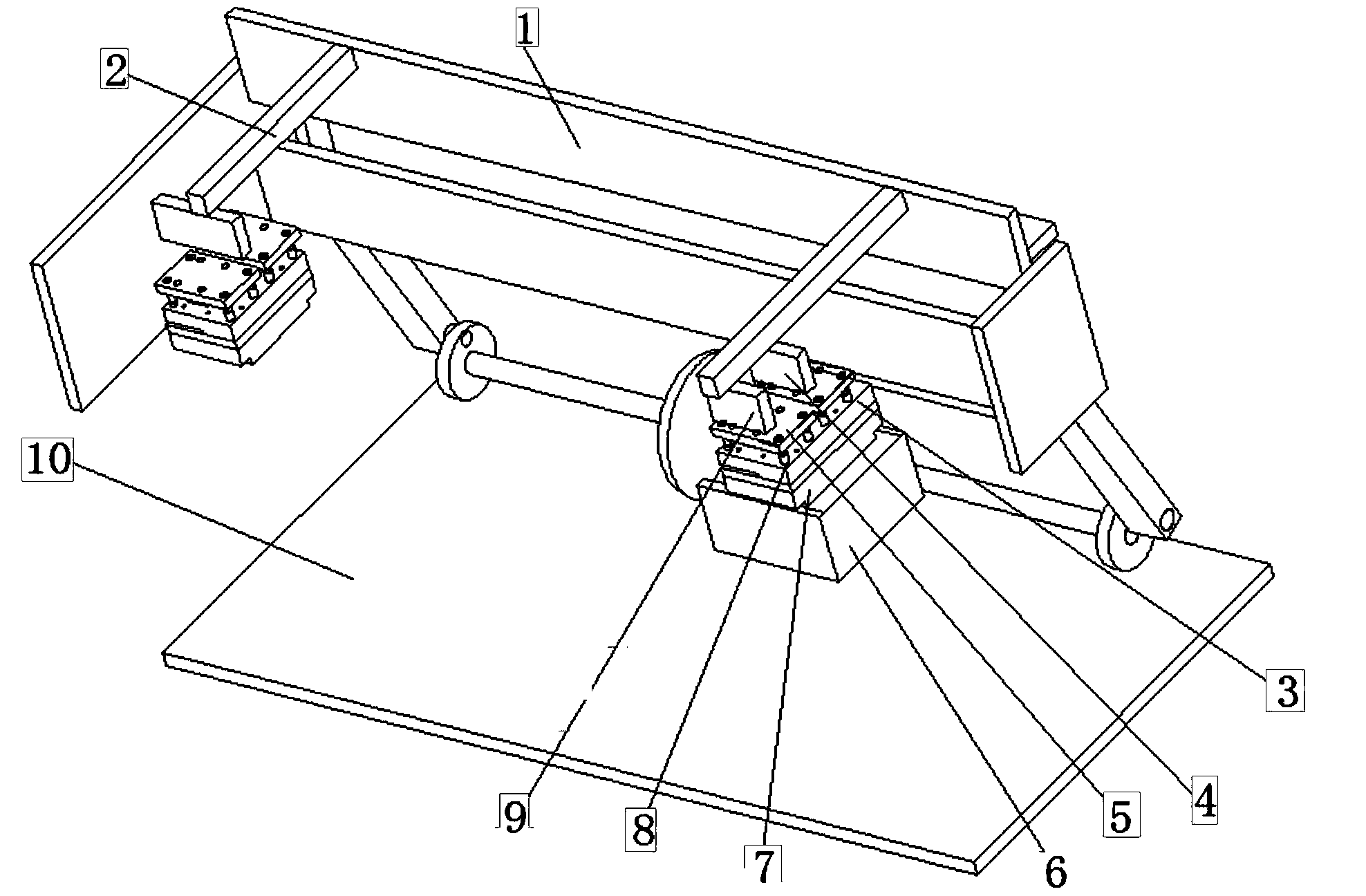
[0037] Embodiment 1; the end of the cylinder shaft extending from the action cylinder is provided with a cylinder gasket 4. The essential technical effect of the technical solutions provided by this office is to provide specific compression solutions, combining figure 1 , figure 2 with Figure 4 , Figure 5 , By using the force device 2 to press the cylinder block 4, the downward force can be realized, and various operation effects can be realized.

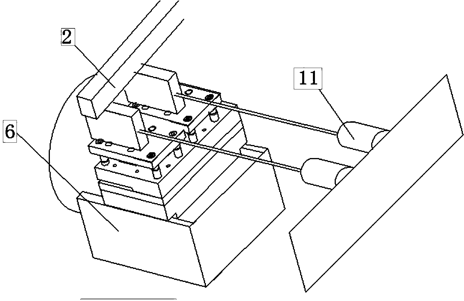
[0038] As an optimization of embodiment 1, the action cylinder is a side cylinder group 11, and the side cylinder group 11 is arranged side by side and installed on a bracket. The cylinder shafts extending from the cylinder shaft are respectively provided with a cylinder head gasket 4 and an adjacent cylinder head gasket 9 There is an upper template 3 under the cylinder head gasket 4 and the adjacent cylinder head gasket 9 respectively, and two upper templates 3 are arranged side by side. Combine figure 2 , And there can be only on...

Embodiment 2

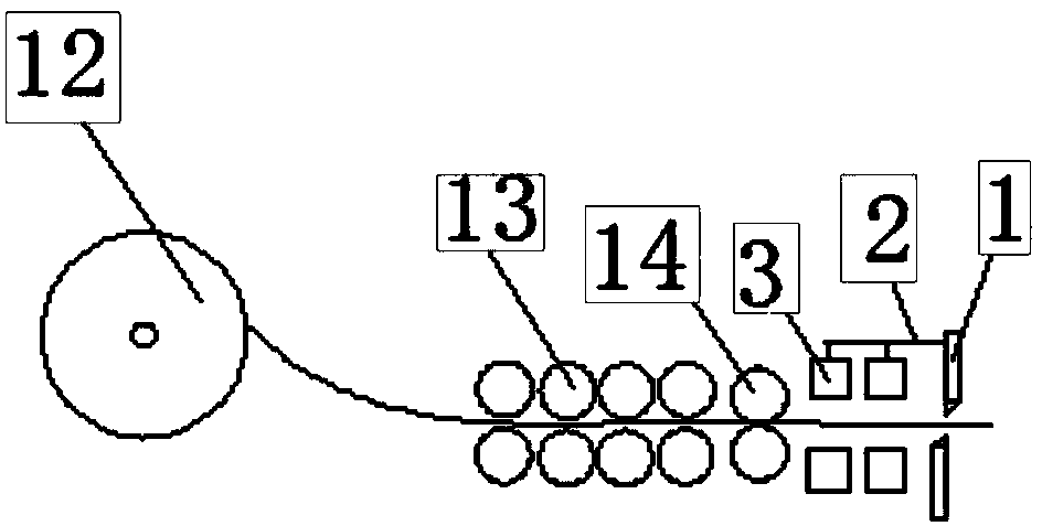
[0039] Example 2, combining Image 6 , The upper template 3 and the lower template 7 placed on the plane are both located on a movable base. The bottom of the movable base includes wheels, and the upper part of the movable base also includes side panels. The side panels have rails, The template 3 can be sleeved on the rail and can move up and down on it, and the shaft of the cylinder is connected to the side plate and can push the side plate to move.

[0040] The overall push-pull method is adopted, so that whether to perform punching with force is optional.

[0041] As a further optimization of Embodiment 1, a slider is included under the lower template 7, the slider is mounted on a rail, the rail is located on the rail platform 6, and the rail platform 6 is fixed on the foundation platform. The essential technical effect of the technical solution here is that the device can process steel plates of different sizes, and it is convenient to change the punching position of the steel ...


PUM


Abstract

The invention relates to the field of machinery, in particular to an air flue plate processing device and an air flue plate processing method. The original fully oil pressure driving production line is created into a mechanical production line, an oil pressure type plate shearing machine is modified into a mechanical plate shearing machine, the comprehensive assistance is realized, meanwhile, large openings and small openings are punched, when the cutting is needed, a template needs to be used for punching, an air cylinder shaft of a moving air cylinder extends out, during the descending cutting of a plate shearing upper knife, an upper template is also driven to be downwards pressed and is in contact with a lower template for punching holes. Compared with the prior art, the air flue plate processing device and the air flue plate processing method adopting the technical scheme have the following beneficial effects that the production efficiency is higher than that of the original oil pressure structure; no oil leaks, and an electromagnetic valve cannot be blocked; the cost (including the manufacturing cost and the processing cost) is reduced; the stability and the uniformity of processed products are better, equipment is not influenced by temperature, and the work of the equipment is stable and reliable.

Description

Technical field [0001] The invention relates to the field of machinery, and in particular to a device and method for processing air duct plates. Background technique [0002] The working principle of the original equipment is to use an oil cylinder to drive the cutter to cut, while a separate oil cylinder drives the upper template and the lower template to squeeze. Due to the high frequency of the cylinder action, this type of equipment frequently produces oil, which makes the oil temperature If it is too high to cause oil leakage, the overflow valve is easy to be blocked, the oil pump is also easily damaged, the working speed is slow, and the working efficiency is not high. Summary of the invention [0003] The purpose of the invention: in order to provide a powerful air duct board processing device and method, the specific purpose is shown in the multiple substantial technical effects in the specific implementation part. [0004] In order to achieve the above objective, the prese...

Claims


Application Information

Patent Timeline
Patent Type & Authority Applications(China)
IPC IPC(8): B23P23/02B23P15/00
CPCB23P23/04B23P15/00
Inventor 张建军
Owner 张建军
Why Eureka
Try Eureka