LED lamp tube

A technology of LED light tubes and LED light strips, which is applied in cooling/heating devices of lighting devices, lighting and heating equipment, semiconductor devices of light-emitting elements, etc., and can solve the problem of strong light absorption and poor light transmission effect of the plastic pipe on the upper shell , poor heat dissipation and other problems, to solve glare and spot light, improve light output efficiency, and reduce the effect of replacement

Inactive Publication Date: 2014-06-18
XIAN JUNXIE OPTOELECTRONICS TECH
View PDF1 Cites 6 Cited by
  • Summary
  • Abstract
  • Description
  • Claims
  • Application Information

AI Technical Summary

Problems solved by technology

[0005] Among them, the first type adopts all-plastic tube, which has poor heat dissipation effect and poor light transmission effect; the second type of lamp housing has good heat dissipation effect, but its cost is high, and the plastic pipe on the upper shell has strong light absorption and poor light transmittance.

Method used


Image

  • LED lamp tube
  • LED lamp tube
  • LED lamp tube

Examples


no. 1 example

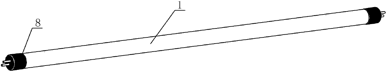
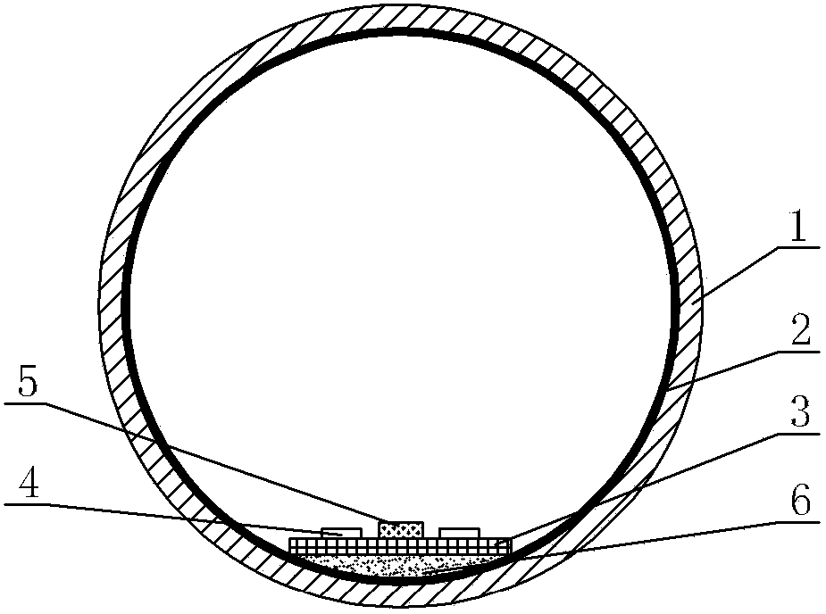
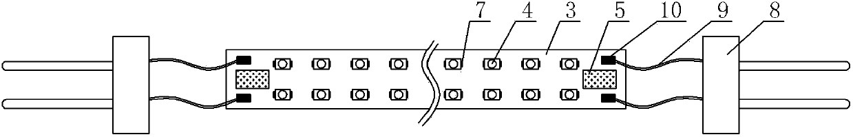
[0025] see Figure 1-Figure 3 , the LED lamp tube includes a glass tube 1, a lamp holder 8 arranged at both ends of the tube, and an LED lamp bar arranged inside it, the inner wall of the glass tube 1 is coated with a light-enhancing heat dissipation film 2, and the LED lamp bar is passed through a high thermal conductivity adhesive Glue 6 is bonded and fixed on the inner wall of glass tube 1 . The light-enhancing and heat-dissipating film 2 is an aluminum-plated layer, or a frosted heat-conducting and light-enhancing adhesive layer, or a nano-adhesive layer that can increase light and dissipate heat. The LED light bar includes a base plate 3 bonded and fixed on the glass tube 1. Several LED light sources 4 connected in parallel (or in series) are welded on the base plate 3. The LED light source 4 is a light-emitting diode, and its pin 7 is connected through tin Wire or solder paste is soldered on the pads 10 of the substrate 3 . The LED light bar is also provided with a dri...

no. 2 example

[0030] see Figure 4 The main difference between this LED light tube and the first embodiment is that the substrate 3 of the LED light bar is packaged with an integrated light source composed of several LED chips 11 connected in parallel (or in series). The LED chip 11 is electrically connected to the energized pad 10 of the substrate 3 through a metal wire 13, and the light-emitting surface 12 of the substrate 3 corresponding to the LED chip 11 is filled with a phosphor adhesive layer 14, and the phosphor adhesive layer 14 covers the LED chip 11. and wrapping the metal wire 13, the driving power supply module 5 can supply power to the LED chip 11 to make the LED chip 11 emit light. Other unmentioned parts are the same as the first embodiment and will not be repeated.


PUM


Abstract

An LED lamp tube comprises a glass tube, lamp bases arranged at two ends and an LED lamp strip arranged in the inside, wherein the inner wall of the glass tube is coated with a brightness-improving heat radiation film, and the LED lamp strip is bonded and fixed on the inner wall of the glass tube through a high-thermal-conductivity adhesive. The brightness-improving heat radiation film is an aluminum coated layer or a frosted heat-conducting brightness-improving adhesive layer or a brightness-improving heat radiation nano adhesive layer. The LED lamp strip comprises a substrate, and a plurality of LED light sources are welded on the substrate, or an integrated light source composed by an LED chip is packaged on the substrate. A drive power source module is further arranged on the LED lamp strip. The light emergence efficiency and a light emergence angle of the LED lamp tube are improved / increased, the irradiation area is large, the glare and light spot problems existing in the LED lamp tube are solved, heat produced by an LED is transferred to the whole glass lamp tube through the substrate, the heat radiation area is increased remarkably, the heat radiation speed of the LED lamp tube is improved, the LED lamp tube can be applicable to a lamp holder of a traditional fluorescent lamp, the universality is greatly improved, and the replacement and usage cost is reduced.

Description

technical field [0001] The invention relates to an LED lamp tube. Background technique [0002] Fluorescent lamps are commonly used lighting fixtures. Traditional fluorescent lamps are filled with fluorescent powder, which contains a variety of toxic heavy metals, which are very harmful to the human body and the ecological environment during manufacture and use. In addition, fluorescent lamps consume a lot of power and have a short service life. , often cannot meet people's needs; at present, traditional fluorescent lamps have been gradually eliminated in the market and replaced by LED lamps. Compared with traditional fluorescent lamps, LED lamps consume less power and have a longer life. [0003] At present, due to the large amount of heat generated by the LED, in order to solve the heat dissipation problem of the known LED lamp tube, the basic structure is to fix the LED on the circuit board. When the LED emits light, the heat generated is transferred to the lamp housing t...

Claims


Application Information

Patent Timeline
Patent Type & Authority Applications(China)
IPC IPC(8): F21S9/00F21V5/00F21V29/00F21V17/10F21V23/00F21V19/00F21Y101/02F21V29/503F21V29/70F21Y103/10F21Y115/10
Inventor 不公告发明人
Owner XIAN JUNXIE OPTOELECTRONICS TECH
Why Eureka
Try Eureka