Electrical impedance tomography imaging plant root system architecture in-situ observation method

An electrical impedance fault, plant root technology, applied in the direction of material resistance, can solve the problems of poor measurement accuracy, inability to distinguish root health status, long time consumption, etc., to achieve strong resistance to external interference, portable and easy-to-operate equipment, and imaging speed. quick effect

Inactive Publication Date: 2014-06-18
李星恕 +1
View PDF5 Cites 11 Cited by
  • Summary
  • Abstract
  • Description
  • Claims
  • Application Information

AI Technical Summary

Problems solved by technology

[0003] However, the common limitations of these observation techniques are: it takes a long time to complete a measurement, and it is impossible to realize real-time monitoring of plant roots. It can only be used to evaluate the root biomass and cannot distinguish the health status of the root system.
[0004] At the same time, they also have their own specific limitations: for example, the microroot canal method cannot conduct comprehensive observation and measurement of the entire root system configuration, but can only achieve two-dimensional and local observation of a specific depth of the root system; the radar signal parameters of ground penetrating radar itself are easily affected. The influence of surrounding...

Method used


Image

  • Electrical impedance tomography imaging plant root system architecture in-situ observation method
  • Electrical impedance tomography imaging plant root system architecture in-situ observation method
  • Electrical impedance tomography imaging plant root system architecture in-situ observation method

Examples


Embodiment Construction

[0036] Below in conjunction with accompanying drawing and specific embodiment, the scheme of the present invention is described in further detail:

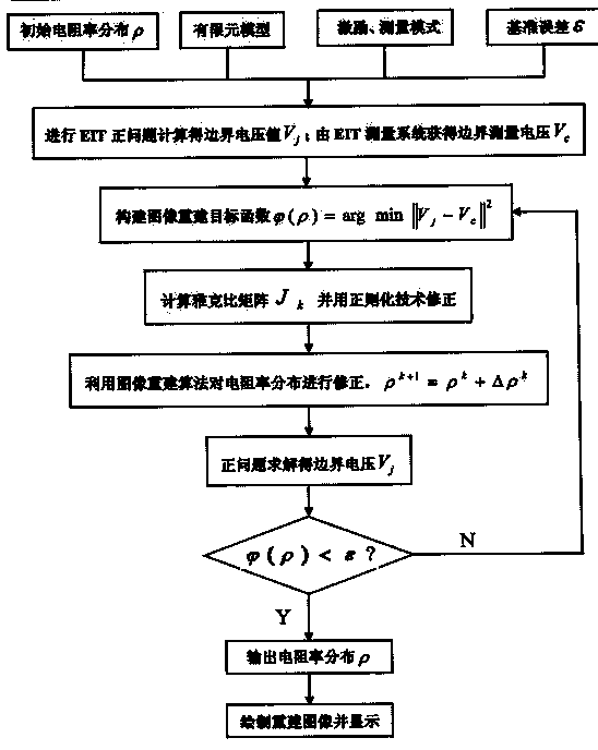
[0037] An electrical impedance tomography method for in-situ observation of plant root architecture, using such as Figure 4 The hardware shown, in which the computer provides the Matlab experimental platform, the LCR impedance tester provides excitation for the experimental system and measures the electrical impedance, multiple high-speed switches control the application of excitation and the selection of voltage (current) measurement electrode pairs, and there are 16 electrodes on the experimental container contact with test subjects. The computer, LCR impedance tester, and multi-channel high-speed switch are connected through the USB / GPIB interface for communication; and the LCR impedance tester and the multi-channel high-speed switch are connected through signal input and output lines; the multi-channel high-speed switch is co...


PUM


Abstract

The invention relates to an electrical impedance tomography imaging plant root system architecture in-situ observation method which comprises the steps of 1, evenly distributing N electrodes in the soil containing a plant root system in a circular shape, sequentially applying sinusoidal alternating current (AC) on two of the electrodes, and measuring the voltage between every two adjacent electrodes in the rest electrodes to obtain voltage data; 2, carrying out finite element mesh partition on the cross section of circumference provided with the electrodes in the soil; 3, carrying out system matrix calculation on the voltage data obtained in the step 1 to obtain the resistivities of all the grids obtained in the step 2, wherein each resistivity represents the resistivity of the corresponding position in the solving domain; imaging by utilizing the resistivity data, setting different colors for units with different resistivities according to the resistivity values of the units by a red, green and blue (RGB) color mode, and judging the different resistivities of all the units according to the colors of the image; according to the difference between the root system and the surrounding soil resistivity, determining the shape and the position of the root system to realize the plant root system architecture in-situ observation.

Description

technical field [0001] The invention relates to the field of identification of plant root system configuration, in particular to an in-situ observation method of plant root system configuration by electrical impedance tomography. Background technique [0002] The existing technologies used to realize in-situ observation and identification of plant root architecture mainly include: microroot canal method, ground penetrating radar (GPR) technology, ray computer tomography (X-CT) technology, and magnetic resonance imaging (MRI) technology. . [0003] However, the common limitations of these observation techniques are that it takes a long time to complete a measurement and cannot realize real-time monitoring of plant roots, and can only be used to evaluate root biomass but not identify root health status. [0004] At the same time, they also have their own specific limitations: for example, the micro-root canal method cannot conduct comprehensive observation and measurement of ...

Claims


Application Information

Patent Timeline
IPC IPC(8): G01N27/04
Inventor 李星恕崔猛杨剑雄熊秀芳
Owner 李星恕
Why Eureka
Try Eureka