Calculating method for propagation delay of electromagnetic wave penetrating through dielectric-slab

A calculation method and technology of propagation delay, applied in radio wave reflection/re-radiation, radio wave measurement system, utilization of re-radiation, etc., can solve problems such as large amount of calculation

Active Publication Date: 2014-06-18
CENT SOUTH UNIV
View PDF2 Cites 1 Cited by
  • Summary
  • Abstract
  • Description
  • Claims
  • Application Information

AI Technical Summary

Problems solved by technology

[0012] The calculation methods of these two time delay values ​​are very computationally intensive, and are not suitable for real-time imaging processing of surface penetrating radar

Method used


Image

  • Calculating method for propagation delay of electromagnetic wave penetrating through dielectric-slab
  • Calculating method for propagation delay of electromagnetic wave penetrating through dielectric-slab
  • Calculating method for propagation delay of electromagnetic wave penetrating through dielectric-slab

Examples


Embodiment 1

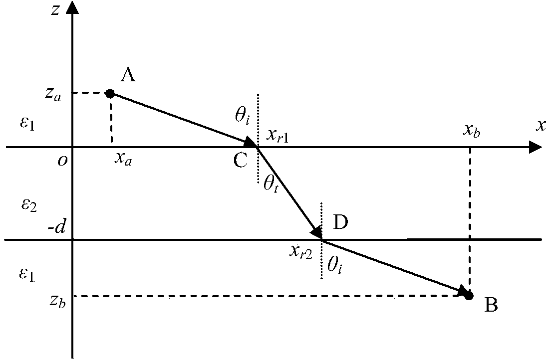
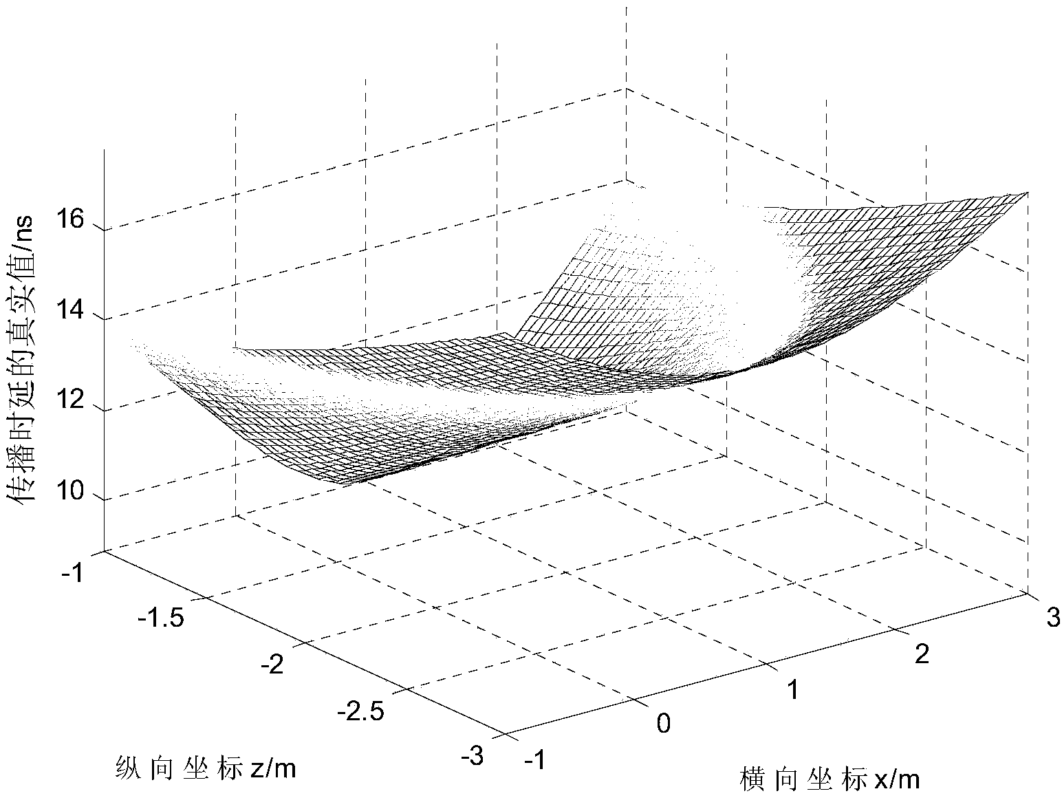
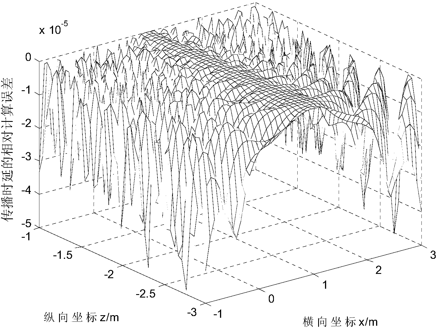
[0048] In this example, the environment on both sides of the dielectric plate is air, ε 1 =1,ε 2 =8, d=-0.5m, the coordinates of the emission point on one side of the dielectric plate are x a = 1 m z a = 0.2 m . The target point area (imaging area) in the other side of the dielectric plate is set to xo ∈ [ - 1 , 3 ] m zo ∈ ...


PUM


Abstract

The invention discloses a calculating method for a propagation delay of an electromagnetic wave penetrating through a dielectric-slab. When the electromagnetic wave bias transmits the dielectric-slab, the propagation path of the electromagnetic wave is divided into three sections, namely, paths propagating on the two sides of the dielectric-slab and a path propagating in the dielectric-slab. The medium environments on the two sides of the dielectric-slab are the same, so that incident angles formed when the electromagnetic wave emits onto the surface of the dielectric-slab and refraction angles formed when the electromagnetic wave transmits from the dielectric-slab are the same, and a unary quartic equation about the horizontal length of the propagation path of the electromagnetic wave in the dielectric-slab is accordingly established. The horizontal length of the propagation path of the electromagnetic wave in the dielectric-slab can be acquired by solving the equation, and the total propagation path and the total propagation delay of the electromagnetic wave penetrating through the dielectric-slab are calculated and acquired. According to the method, the traditional delay calculating method for two-dimensional searching or solving a binary quartic equation set is avoided, the operand is greatly reduced, and the method is fit for the real-time positioning and high-resolution imaging process for a target during a surface-layer-transmitting radar detection process.

Description

technical field [0001] The invention belongs to the technical field of surface-penetrating radar detection and imaging, and in particular relates to a calculation method for propagation time delay of electromagnetic waves penetrating a dielectric plate. Background technique [0002] Surface penetrating radar is an effective non-destructive detection technology. It emits electromagnetic waves to the detection area and receives scattered echoes through airspace scanning, which can realize imaging processing inside the surface shielded area and obtain hidden target parameters in unknown areas, that is, target distribution information and scattering intensity information, which can be effectively applied behind walls Personnel detection, personnel positioning in ruins and other occasions. [0003] There are many positioning and imaging methods for surface penetrating radar, and one of the key processing steps is the calculation of electromagnetic wave propagation delay. Accord...

Claims


Application Information

Patent Timeline
Patent Type & Authority Applications(China)
IPC IPC(8): G01S7/02G01S13/89
CPCG01S13/887G01S13/89
Inventor 雷文太
Owner CENT SOUTH UNIV
Why Eureka
Try Eureka