Integrated magnetic structure

A magnetic integration, magnetic core technology, applied in the electromagnetic field, can solve the problems of loss and volume increase, increase the air gap, insufficient use of some magnetic cores of the transformer, etc., to reduce the volume, reduce the volume of the magnetic core, and increase the power The effect of density

Inactive Publication Date: 2014-06-18
TONGJI UNIV
View PDF4 Cites 19 Cited by
  • Summary
  • Abstract
  • Description
  • Claims
  • Application Information

AI Technical Summary

Problems solved by technology

This structure can realize the decoupling integration of the inductor and the transformer. The disadvantage is that in the actual use process, the transformer part of the magnetic core usually does not contain a DC magnetic flux component, but there will be a large AC magnetic flux component. In order to control the loss of the transformer , the AC flux component will be limited, and the limit value is usually much lower than the saturati

Method used


Image

  • Integrated magnetic structure
  • Integrated magnetic structure
  • Integrated magnetic structure

Examples


Embodiment Construction

[0024] The present invention will be further described below in conjunction with the embodiments shown in the accompanying drawings.

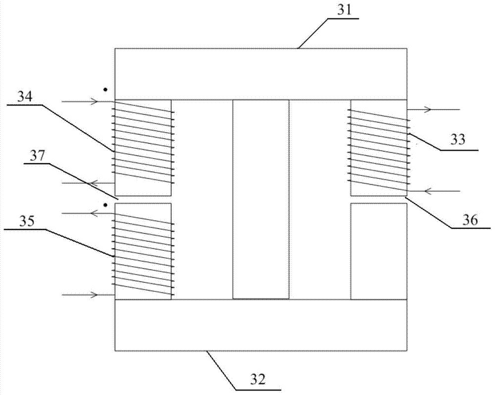
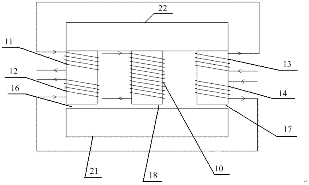
[0025] In order to reduce the overall volume of the magnetic element and increase the power density of the power electronic converter, the present invention proposes a magnetic integration structure that can make full use of the magnetic core material and is beneficial to reduce the volume of the magnetic element.

[0026] Such as Figure 2a Shown is a schematic structural diagram of the magnetic integration structure in the first embodiment of the present invention. In this embodiment, the magnetic integration structure is used as an example for description of the magnetic integration structure of a transformer and an inductor. The magnetic integration structure includes a flat "Sun"-shaped magnetic core, which is formed by stacking an E-shaped magnetic core 22 and an I-shaped magnetic core 21 . The inductance winding is wound on the middle ...


PUM


Abstract

The invention discloses an integrated magnetic structure, and belongs to the technical field of electromagnetism. The integrated magnetic structure comprises a horizontal magnetic core shaped like a Chinese character Ri, first and second side column windings wound on a left side column, third and fourth side column windings wound on a right side column and a middle column winding wound on a middle column, wherein the first and third side column windings are connected and forwards coupled; the second and fourth side column windings are connected and forwards coupled. When the integrated magnetic structure is applied to the integration of a transformer and an inductor, magnetic flux generated by a winding of the inductor passes through a magnetic circuit of the transformer, so that a magnetic core material can be fully utilized, and the size of a magnetic core can be reduced; when the integrated magnetic structure is applied to the integration of a common mode choke and a differential mode choke, magnetic flux generated by a winding of the differential mode choke passes through the common mode choke part, so that the whole magnetic core is fully utilized, and the size of a filter is reduced; moreover, the common mode choke and the differential mode choke are decoupled, and can be independently regulated without influence.

Description

technical field [0001] The invention belongs to the field of electromagnetic technology and relates to a magnetic integration structure. Background technique [0002] In many fields such as aerospace, electric vehicles, and photovoltaic power generation, high-power power electronic converters are indispensable components. How to effectively reduce the volume of magnetic components, increase power density, improve conversion efficiency, and improve electromagnetic interference (EMI) is not only related to the normal operation of the converter itself, but also related to the optimization of the overall performance of the system and the improvement of energy utilization efficiency. Improve and control the stable and reliable operation of the part. Integrating the transformer and inductor in the converter and the differential mode and common mode inductors in the filter can reduce the overall volume of the magnetic components and increase the power density of the power electron...

Claims


Application Information

Patent Timeline
IPC IPC(8): H01F27/24H01F27/30H01F3/14H01F38/00
Inventor 张逸成杨晓盛韦莉姚勇涛李志栋张佳佳叶尚斌刘帅詹地夫顾帅沈玉琢
Owner TONGJI UNIV
Why Eureka
Try Eureka