Ultrasound diagnostic device and ultrasound diagnostic device control method

A diagnostic device and ultrasonic technology, applied in ultrasonic/sonic/infrasound equipment control, sonic diagnosis, infrasound diagnosis, etc., can solve the problems of complicated operation and achieve the effect of simple operation

Inactive Publication Date: 2014-06-18
KONICA MINOLTA INC
View PDF9 Cites 4 Cited by
  • Summary
  • Abstract
  • Description
  • Claims
  • Application Information

AI Technical Summary

Problems solved by technology

[0006] The operation of determining the ROI 13 for specifying the IMT measurement range must be performed manually, and the operation is complicated

Method used


Image

  • Ultrasound diagnostic device and ultrasound diagnostic device control method
  • Ultrasound diagnostic device and ultrasound diagnostic device control method
  • Ultrasound diagnostic device and ultrasound diagnostic device control method

Examples


Embodiment approach 1

[0059] Hereinafter, an ultrasonic diagnostic apparatus according to one aspect of Embodiment 1 will be described with reference to the drawings.

[0060]

[0061] (the whole frame)

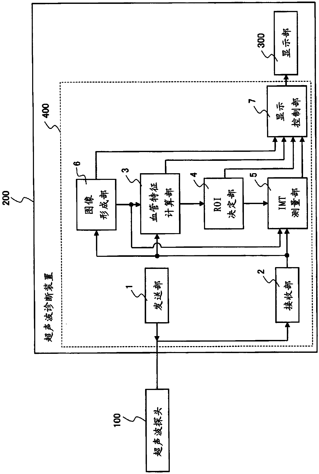
[0062] figure 1 It is a block diagram showing the configuration of the ultrasonic diagnostic apparatus 200 according to one aspect of the first embodiment. The ultrasonic diagnostic apparatus 200 is configured to be electrically connectable to the ultrasonic probe 100 that transmits and receives ultrasonic waves to and from a subject. figure 1 A state in which the ultrasonic probe 100 is connected to the ultrasonic diagnostic apparatus 200 is shown. The ultrasonic diagnostic apparatus 200 includes a controller 400 and a display unit 300 . The controller 400 includes a transmission unit 1 , a reception unit 2 , a blood vessel feature calculation unit 3 , an ROI determination unit 4 , an IMT measurement unit 5 , an image forming unit 6 , and a display control unit 7 .

[0063] (sending part ...

Embodiment approach 2

[0107]

[0108] (the whole frame)

[0109] The ultrasonic diagnostic apparatus 201 according to the second embodiment is characterized in that the blood vessel feature calculation unit 3 in the ultrasonic diagnostic apparatus 200 according to the first embodiment is changed to detect the common carotid artery CCA and The blood vessel feature calculation unit 15 of the boundary position of the bulb of the common carotid artery. In the ultrasonic diagnostic apparatus 200 according to Embodiment 1, the CCA-Bulb boundary 14 is detected based on the change in the diameter of the blood vessel in the vicinity of the CCA-Bulb boundary 14 . Embodiment 2 The CCA-Bulb boundary 14 is detected according to the change of the coordinate position of the blood vessel wall. In the ultrasonic diagnostic apparatus 201 according to the second embodiment, components other than the blood vessel feature calculation unit 3 and figure 1 The constituent elements shown in the block diagram of the ul...

Embodiment approach 3

[0129]

[0130] (the whole frame)

[0131]The ultrasonic diagnostic apparatus 202 according to the third embodiment is characterized in that the blood vessel feature calculation unit 3 in the ultrasonic diagnostic apparatus 200 according to the first embodiment is changed to detect the common carotid artery based on the variation of the blood vessel diameter due to the pulsation of the blood vessel. The blood vessel feature calculation unit 16 of the boundary position between the CCA and the bulb of the common carotid artery. The amount of change in the diameter of the blood vessel due to the pulsation of the blood vessel changes from the center to the periphery, and becomes larger around the vicinity of the CCA-Bulb boundary 14 . Therefore, the ultrasonic diagnostic apparatus 202 according to the third embodiment detects the change amount of the blood vessel diameter due to the pulsation along the longitudinal direction, and detects the CCA-Bulb boundary 14 by detecting the...


PUM


Abstract

Provided is an ultrasound diagnostic device which is configured to be connectable to an ultrasound probe, and with which IMT of a carotid artery wall is measured, comprising: a transmission unit which supplies to an ultrasound probe a transmission signal for causing the ultrasound probe to transmit ultrasound along a longitudinal cross-section of a carotid artery; a receiving unit which receives a signal based on the reflected ultrasound which the ultrasound probe receives from the carotid artery and generates a received signal; a blood vessel characteristic computation unit which, on the basis of the received signal, extracts location information which includes a location of each part which configures the carotid artery wall and / or a relative relation between the locations, and detects a boundary location between the common carotid artery and the bulb of the carotid artery on the basis of the longitudinal change of the carotid artery of the location information; an ROI establishment unit which, using the boundary location as a reference, establishes an ROI which defines the measurement range for measuring the IMT; and an IMT measurement unit which measures the IMT of the blood vessel wall which is included in the ROI.

Description

technical field [0001] The present invention relates to an ultrasonic diagnostic device and a control method of the ultrasonic diagnostic device, in particular to a diagnostic technique for early detection of arteriosclerotic carotid artery. Background technique [0002] In recent years, the number of patients suffering from circulatory diseases such as ischemic diseases such as cerebral infarction and myocardial infarction is increasing. To prevent these diseases, it is important to detect the signs of arteriosclerosis early and treat them. [0003] As an index for judging arteriosclerosis, attention has been paid to the measurement of the intima-media thickness (Intima-Media Thickness: hereinafter, abbreviated as IMT.) of the carotid artery. As this measurement method, ultrasonography has become popular because it can be performed non-invasively and simply. In this IMT measurement, the reason why the carotid artery is used as the measurement object is because the carotid...

Claims


Application Information

Patent Timeline
Patent Type & Authority Applications(China)
IPC IPC(8): A61B8/00
CPCA61B8/5223A61B8/463A61B8/54A61B8/469A61B8/085A61B8/14A61B8/5207A61B8/0891G16H50/30Y02A90/10
Inventor 大河内惇也铃木隆夫
Owner KONICA MINOLTA INC
Why Eureka
Try Eureka