Pneumatic bending machine

A bending machine and pneumatic technology, applied in the field of processing machinery, can solve the problems of complex structure of hydraulic bending machine, easy damage of thin plate parts, high energy consumption of bending machine, etc., to improve labor intensity, not easy to damage parts, Guarantee the effect of bending effect

Active Publication Date: 2014-06-25
GUANGDONG ENAITER ELECTRICAL APPLIANCES CO LTD
View PDF6 Cites 2 Cited by
  • Summary
  • Abstract
  • Description
  • Claims
  • Application Information

AI Technical Summary

Problems solved by technology

[0005] The motor-driven bending machine consumes a lot of energy and has low efficiency; the structure of the hydraulic bending machine is more complicated and the cost is higher; while the existing pneumatic bending machine is driven by the air pressure control cylinder, the structure is simple and the energy consumption is low , but the pressure head part of the bending part is driven by the cylinder faster, and the action is too fast, and some thin plate parts are easy to be damaged when bending

Method used


Image

  • Pneumatic bending machine
  • Pneumatic bending machine
  • Pneumatic bending machine

Examples


Embodiment Construction

[0037] The following will clearly and completely describe the technical solutions in the embodiments of the present invention with reference to the accompanying drawings in the embodiments of the present invention. Obviously, the described embodiments are only some, not all, embodiments of the present invention. Based on the embodiments of the present invention, all other embodiments obtained by persons of ordinary skill in the art without creative efforts fall within the protection scope of the present invention.

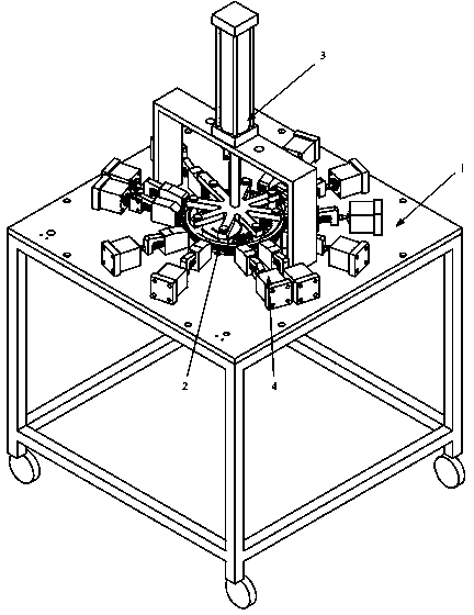
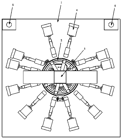
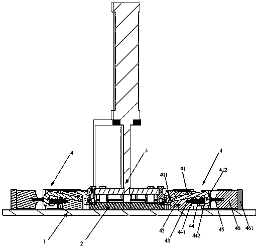
[0038] refer to Figure 1~2 , the invention discloses a pneumatic bending machine, which includes a frame 1, a positioning device 2, a pneumatic preloading device 3, a pneumatic bending device 4 and an electric control device 5, wherein:

[0039] The positioning device 2 is arranged on the frame 1 for carrying the product to be bent;

[0040] The pneumatic preloading device 3 is used to press the product to be bent onto the positioning device by moving up and down...


PUM


Abstract

The invention discloses a pneumatic bending machine. The pneumatic bending machine comprises a rack, a locating device, a pneumatic prepressing device, a pneumatic bending device and an electronic control device, wherein the locating device is arranged on the rack and is used for bearing a product to be bent, the pneumatic prepressing device is used for tightly pressing the product to be bent on the locating device through vertical movement, the pneumatic bending device is used for bending the product to be bent through stretching and contraction movement, the electronic control device is electrically connected with the pneumatic prepressing device and the pneumatic bending device, and is used for having control over movement of the pneumatic prepressing device and movement of the pneumatic bending device, the pneumatic bending device comprises bending plunger chips, a plunger chip base, elastic component locating pins, elastic components, stroke control pins and bending air cylinders fixedly connected with the stroke control pins, guide grooves are formed in the plunger chip base, one end of each bending plunger chip penetrates through the corresponding guide groove to be opposite to the product to be bent, the other end of each bending plunger chip is close to the corresponding stroke control pin, the elastic component locating pins are fixed to the plunger chip base, each elastic component locating pin is sleeved with one end of the corresponding elastic component, and the other end of each elastic component abuts against the other end of the corresponding bending plunger chip.

Description

technical field [0001] The invention relates to the technical field of processing machinery, in particular to a pneumatic bending machine. [0002] Background technique [0003] At present, the processing pressure cover frame assembly uses manual pressing of the detachable aluminum cover. This method is slow in efficiency and labor-intensive, and the quality is greatly affected by the operator's proficiency and is unstable. [0004] Now most of the parts of various equipment are produced by various processing equipment, such as various lathes, milling machines, grinding machines and machining centers used for material removal processing, and various machines used to connect various parts Welding equipment, etc., and other painting and blackening equipment used to treat the surface of parts, etc. When parts need to be bent, we often use bending machines. According to different driving methods, they are divided into motor drive bending machines, hydraulic bending machines...

Claims


Application Information

Patent Timeline
Patent Type & Authority Applications(China)
IPC IPC(8): B21D11/00
Inventor 杨广良毛庆成
Owner GUANGDONG ENAITER ELECTRICAL APPLIANCES CO LTD
Why Eureka
Try Eureka