
Oxygen reduction device and refrigerator

A technology for oxygen reduction devices and refrigerators, which can be used in household refrigeration devices, lighting and heating equipment, applications, etc., and can solve problems such as low durability of oxygen reduction devices

Active Publication Date: 2016-11-16
TOSHIBA LIFESTYLE PROD & SERVICES CORP
View PDF4 Cites 0 Cited by
  • Summary
  • Abstract
  • Description
  • Claims
  • Application Information

AI Technical Summary

Problems solved by technology

Due to this, peeling may occur at the joint surface between the electrolyte membrane of the oxygen reduction unit and the anode, and the durability of the oxygen reduction device may decrease.

Method used

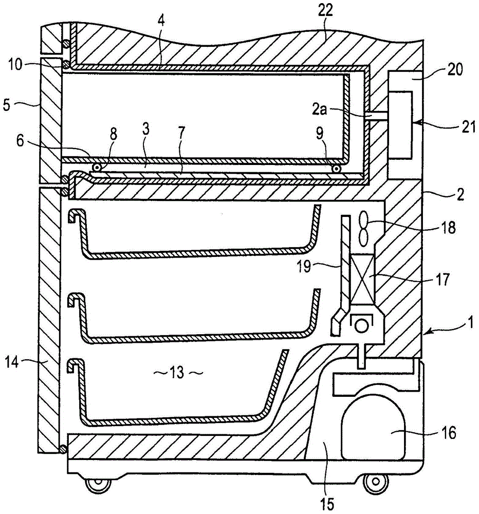

Image

  • Oxygen reduction device and refrigerator
  • Oxygen reduction device and refrigerator
  • Oxygen reduction device and refrigerator

Examples


Embodiment 1)

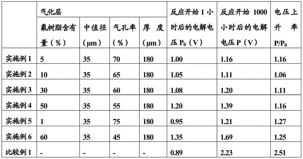
[0150] In Example 1, the vaporized layer 38 was obtained by the following manufacturing method. First, carbon paper having a thickness of 180 μm was immersed in a PTFE dispersion solution for 1 minute, and then dried overnight at room temperature. Next, the thus-dried carbon paper was fired at 380° C. for 10 minutes in an argon atmosphere. Thereby, vaporized layer 38 including carbon paper with a content of 5 wt% of PTFE as a fluororesin was obtained. The vaporized layer 38 was evaluated by pore distribution measurement. As a result, the vaporized layer 38 had a median diameter of 35 μm and a porosity of 70%.

Embodiment 1

[0152] Evaluations in Example 1 are as follows.

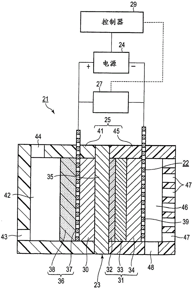
[0153] The oxygen reduction stack 22 is interposed between the first container member 41 and the second container member 45 , and these are connected to form the oxygen reduction container 25 . Thus, the oxygen reduction device 21 is produced. The anode collector layer 37 and the cathode collector layer 39 of this device were connected to the power source 24 . In the evaluation of the oxygen reducing device 21, the anode chamber 42 of the first container part 41 containing the anode 30 is filled with water (liquid), and air is supplied to the cathode chamber 46 of the second container part 45 containing the cathode 31 by active breathing. .

[0154]In such a state, a voltage is applied from the power source 24 to the oxygen reduction unit 23 and controlled so that the reaction current becomes a constant current. This constant current control is performed by, for example, a voltmeter 27 (refer to figure 2 ) to detect the vo...

Embodiment 2)

[0156] In the same manner as in Example 1, a gasification layer 38 made of carbon paper having a thickness of 180 μm and a PTFE content of 10 wt % was produced and obtained. The gasification layer 38 was evaluated by pore distribution measurement, and the gasification layer 38 had a median diameter of 35 μm and a porosity of 65%. The same operation as in Example 1 was carried out to fabricate an oxygen reduction device having the gasification layer 38, and the oxygen reduction reaction was performed by the same operation as in Example 1, and the electrolysis voltage was measured 1 hour and 1000 hours after the start of the reaction. The results are shown in Tables 1 to 4.


PUM

PropertyMeasurementUnit
thicknessaaaaaaaaaa
thicknessaaaaaaaaaa
particle sizeaaaaaaaaaa

Abstract

PROBLEM TO BE SOLVED: To provide an oxygen decreasing device which can control performance deterioration due to cathode flooding phenomena and impurity ions and can also control the deterioration of durability resulting from the exfoliation between an anode and an electrolyte film.SOLUTION: The oxygen decreasing device includes an oxygen decreasing cell, an electrode assembly, and cathode current-collecting layer. The oxygen decreasing cell includes an anode in which a catalyst which oxidizes the water vapor supplied is contained, a cathode which has the cathode catalyst layer in which the catalyst which reduces the oxygen is contained, and an electrolyte film held between the anode and the cathode. The electrolyte film has proton conductivity. The electrode assembly is arranged across the anode between the electrolyte film. The electrode assembly includes the anode current-collecting layer and a vaporizing layer to which water is supplied. The vaporizing layer is arranged at least on one surface of both surfaces of anode current-collecting layer. The vaporizing layer evaporates the water supplied to the layer to water vapor in order to supply to the anode. It is characterized to arrange the cathode current-collecting layer across the cathode between the electrolyte film.

Description

[0001] References to related applications [0002] This application is based on Japanese Patent Application No. 2012-246192 (filing date: November 8, 2012), and enjoys the priority of this application. This application incorporates the entire contents of this application by reference thereto. technical field [0003] Embodiments of the present invention relate to an oxygen reduction device for reducing oxygen concentration and a refrigerator including the device. Background technique [0004] In order to improve the preservation property of foodstuffs, etc., an oxygen reduction device that reduces the oxygen concentration in a storage space (oxygen reduction space) by using an electrochemical reaction using an electrolyte membrane has been proposed. [0005] This device includes an oxygen reduction cell (cell) in which a polymer electrolyte membrane having proton (proton) conductivity is sandwiched between an anode (anode) and a cathode (cathode). This unit is arranged so ...

Claims


Application Information

Patent Timeline
Patent Type & Authority Patents(China)
IPC IPC(8): C25B9/00C25B1/00F25D23/00
CPCB01D53/32F25D23/00
Inventor 田村淳赤坂芳浩深泽大志八木亮介吉永典裕
Owner TOSHIBA LIFESTYLE PROD & SERVICES CORP
Learn More