Energy storage device, system having an energy storage device, and method for operating an energy storage device

An energy storage and energy supply technology, applied in control systems, circuit devices, battery circuit devices, etc., to achieve the effect of improving actual power and availability, saving storage capacity and computing capacity

Active Publication Date: 2014-06-25
ROBERT BOSCH GMBH +1
View PDF8 Cites 5 Cited by
  • Summary
  • Abstract
  • Description
  • Claims
  • Application Information

AI Technical Summary

Problems solved by technology

The cell-voltage-based balancing methods known from the prior art do not distinguish here whether the imbalance is caused by a high power output for a short time or by a low power output for a long time

Method used


Image

  • Energy storage device, system having an energy storage device, and method for operating an energy storage device
  • Energy storage device, system having an energy storage device, and method for operating an energy storage device
  • Energy storage device, system having an energy storage device, and method for operating an energy storage device

Examples


Embodiment Construction

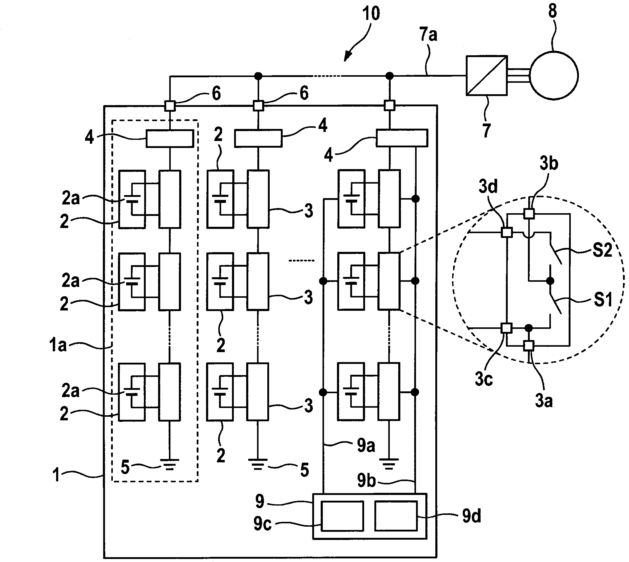
[0021] figure 1 A schematic diagram of a system 10 with an energy storage device 1 is shown. The energy storage device 1 comprises a plurality of energy supply branches 1 a connected in parallel. For example in figure 1 Three energy supply branches 1 a are shown in , wherein any other number of energy supply branches 1 a is likewise possible. For clarity of the drawing, only the energy supply branch 1a on the left is marked as such.

[0022] Each of the energy supply branches 1 a is connected to an associated output connection 6 , each output connection being connected to a supply voltage conductor 7 a of an inverter 7 . In this case, a branch voltage can be generated at each of the output terminals 6 by the energy supply branch 1 a connected thereto. The inverter 7 can convert the power supply voltage provided by the energy storage device 1 on the power supply voltage wire 7 a into a q-phase AC voltage, and then transmit the q-phase AC voltage to the q-phase motor 8 .

...


PUM


Abstract

The invention relates to an energy storage device (1) for generating an n-phase supply voltage, wherein n >= 1, comprising a plurality of energy supply branches (1a) that are connected in parallel, each of which is connected to an output connector (6) of the energy storage device (1). Each of the energy supply branches (1a) is provided with a plurality of energy storage modules (2) that are connected in series, each having at least one energy storage cell (2a), and comprising a plurality of coupling modules (3) connected to one of the plurality of energy storage modules (2), respectively, each configured to couple, or to bridge, the connected energy storage module (2) with the energy supply branch (1a). The energy storage device further comprises a control system (9), which is connected to the coupling modules (3), and which is configured to actuate each of the coupling modules (3) as a function of a value of the aging functions of each energy storage module (2) for coupling each of the connected energy storage modules (2) with one of the plurality of energy storage branches (1a), and to turn the energy supply branches (1a) on or off by way of actuating the branch coupling modules (4) as a function of the sum of the aging functions of the energy storage modules (2) in the respective branches (1a), and as a function of the load demand of an electric consumer (8).

Description

technical field [0001] The invention relates to an energy storage device, a system with the energy storage device and a method for driving the energy storage device. Background technique [0002] In the future, both in static applications such as wind power generation equipment or solar energy equipment, or in vehicles such as hybrid vehicles or electric vehicles, there will be more applications that combine electric operation technology with new energy storage technologies. Power Systems. For example, electric motors are driven today by means of battery cells assembled in groups, wherein a downstream connected inverter supplies the electric motor's supply voltage. [0003] For example, in the case of a three-phase motor or an AC current supply at the supply connection of a three-phase power supply network, the DC voltage provided by the DC voltage intermediate circuit is converted into a three-phase AC voltage by a frequency converter in the form of a pulse inverter. The ...

Claims


Application Information

Patent Timeline
Patent Type & Authority Applications(China)
IPC IPC(8): B60L11/18H02P27/06H02J7/00
CPCH02P27/06Y02E60/10H01M10/482H01M10/425H01M2220/10
Inventor M·克劳斯纳V·登纳S·布茨曼
Owner ROBERT BOSCH GMBH
Why Eureka
Try Eureka