anesthesia vaporizer

An anesthesia evaporator and evaporation chamber technology, applied in the field of anesthesia evaporators, can solve the problems of mixed anesthesia vapor concentration changes, untimely transmission of temperature, potential safety hazards, etc., to avoid leakage of anesthesia, stable and consistent concentration, and large opening and closing Effect

Active Publication Date: 2016-04-20
BEIJING AEONMED
View PDF9 Cites 0 Cited by
  • Summary
  • Abstract
  • Description
  • Claims
  • Application Information

AI Technical Summary

Problems solved by technology

[0003] The existing anesthesia vaporizers have at least the following defects: 1. Most anesthesia vaporizers do not have a transportation position, and the anesthetic agent in the vaporizer needs to be poured out in advance during transportation to prevent the anesthetic agent from leaking during transportation. It means that the evaporator is in a specific position, and the transportation will not cause the anesthetic agent to leak; some anesthesia evaporators have a transportation position, and the transportation position is used in conjunction with an additional independently set sliding valve and the evaporator air control valve, but the structure is relatively complicated. The defects of many parts and high cost;
[0004] 2. When the anesthesia evaporator is in the zero position, that is, when the anesthesia evaporator is in a non-working state, the evaporation pressure in the evaporation chamber cannot be discharged, so that there is always a certain evaporation pressure in the evaporation chamber. When the evaporator is used urgently, it will affect The concentration of anesthetic vapors when switched on, which may cause danger;
[0005] 3. The flow control of the fresh gas is unstable after the temperature of the anesthetic agent changes, and the air resistance of the temperature compensation unit or the temperature control valve changes after a long time of use, which in turn leads to a change in the concentration of the mixed anesthetic vapor output by the evaporator, which brings safety hazards to the use; At the same time, the temperature sensing device in the temperature compensation unit or the temperature control valve is far away from the bottom of the evaporation chamber of the evaporator, and the temperature cannot be transmitted to the temperature compensation unit or the temperature control valve in time.

Method used


Image

  • anesthesia vaporizer
  • anesthesia vaporizer
  • anesthesia vaporizer

Examples


Embodiment Construction

[0045] The technical solutions of the present invention will be further described below in conjunction with the accompanying drawings and through specific implementation methods.

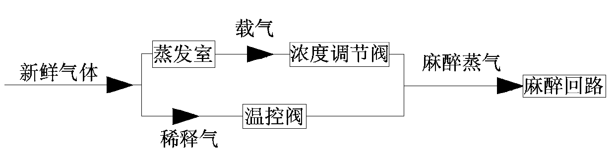
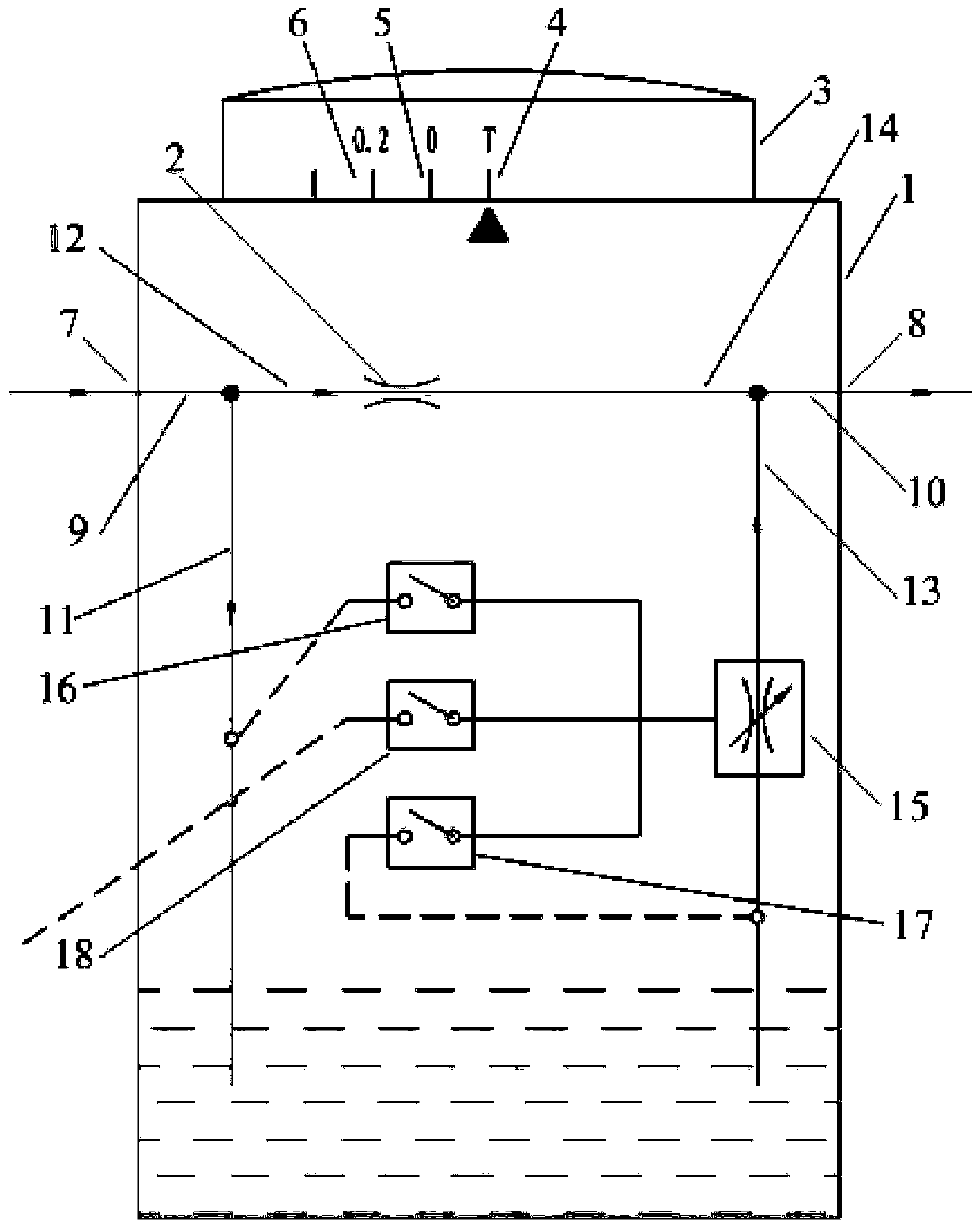
[0046] Such as figure 2 As shown, an anesthesia vaporizer includes an evaporation chamber 1, a dial 3, a temperature control valve 2 and a three-station switching device. The anesthesia vaporizer has a transport position 4, a zero position 5, a concentration position 6, and an evaporation chamber 1. It has a fresh gas inlet 7 and an anesthetic steam outlet 8. The evaporation chamber 1 is provided with a first gas path 9 connected to the fresh gas inlet 7 and a second gas path 10 connected to the anesthetic steam outlet 8. The first gas path 9 is evaporated The chamber 1 is branched into the first branch gas path 11 and the second branch gas path 12, and the third branch gas path 13 and the fourth branch gas path 14 are also set in the evaporation chamber 1, and the two branch gas paths are combined...


PUM


Abstract

The invention discloses an anesthetic evaporator which comprises an evaporation chamber. The anesthetic evaporator is characterized in that the anesthetic evaporator has three stations and comprises a three-station switching device, the three stations include a concentration station, a zero station and a transportation station, and the concentration station is used for regulating the concentration of anesthetic steam outputted by the anesthetic evaporator; the evaporation chamber can be communicated with an external environment via the zero station when the anesthetic evaporator is in a non-working state; the evaporation chamber can form a closed space under the effect of the transportation station; the three-station switching device is used for switching the anesthetic evaporator at the transportation station to the concentration station via the zero station. The anesthetic evaporator has the advantages that a valve plate of a concentration regulating valve rotates relative to a valve seat, so that the three stations can be switched over, and the problem that the internal evaporation pressure of an existing evaporation chamber cannot be effectively relieved when an existing evaporator does not have a transportation station and a zero station can be effectively solved on the premise that the quantity of components is not increased and the cost is saved.

Description

technical field [0001] The invention relates to the technical field of anesthesia vaporizers, in particular to an anesthesia vaporizer with a transport position. Background technique [0002] The anesthesia vaporizer is an important part of the anesthesia machine. Its quality not only marks the level of the anesthesia machine, but also relates to the success or failure of inhalation anesthesia, directly related to the safety of the patient. Liquid volatile anesthetics, such as amflurane and isoflurane, are not allowed to enter the respiratory tract directly, nor are they allowed to enter the respiratory tract in the form of saturated vapor, because most people can achieve anesthesia at a very low partial pressure of the brain. Anesthetics have a relatively high saturated vapor pressure, for example, halothane is 32.4kPa at 20°C, but the partial pressure of the brain that produces anesthesia is only less than 2.27kPa. Anesthesia vaporizer is a device that can convert liquid ...

Claims


Application Information

Patent Timeline
Patent Type & Authority Patents(China)
IPC IPC(8): A61M16/18
Inventor 郑殿会韩果正
Owner BEIJING AEONMED
Why Eureka
Try Eureka