Automatic feeding machine
A technology of automatic feeding and transmission mechanism, used in metal processing machinery parts, metal processing equipment, feeding devices, etc., can solve the problem of high maintenance costs, and achieve the effect of simplifying equipment and reducing costs
- Summary
- Abstract
- Description
- Claims
- Application Information
AI Technical Summary
Problems solved by technology
Method used
Image

Examples
Embodiment 1
[0027] Example 1, the square hole processing of the supply column of the medical pendant.
[0028] Figure 1-6 It is a structural schematic diagram of the automatic feeder and its components provided in Embodiment 1 of the present invention.
[0029] An automatic feeding machine includes a transmission mechanism, a power source and a frame supporting the transmission mechanism and the power source.
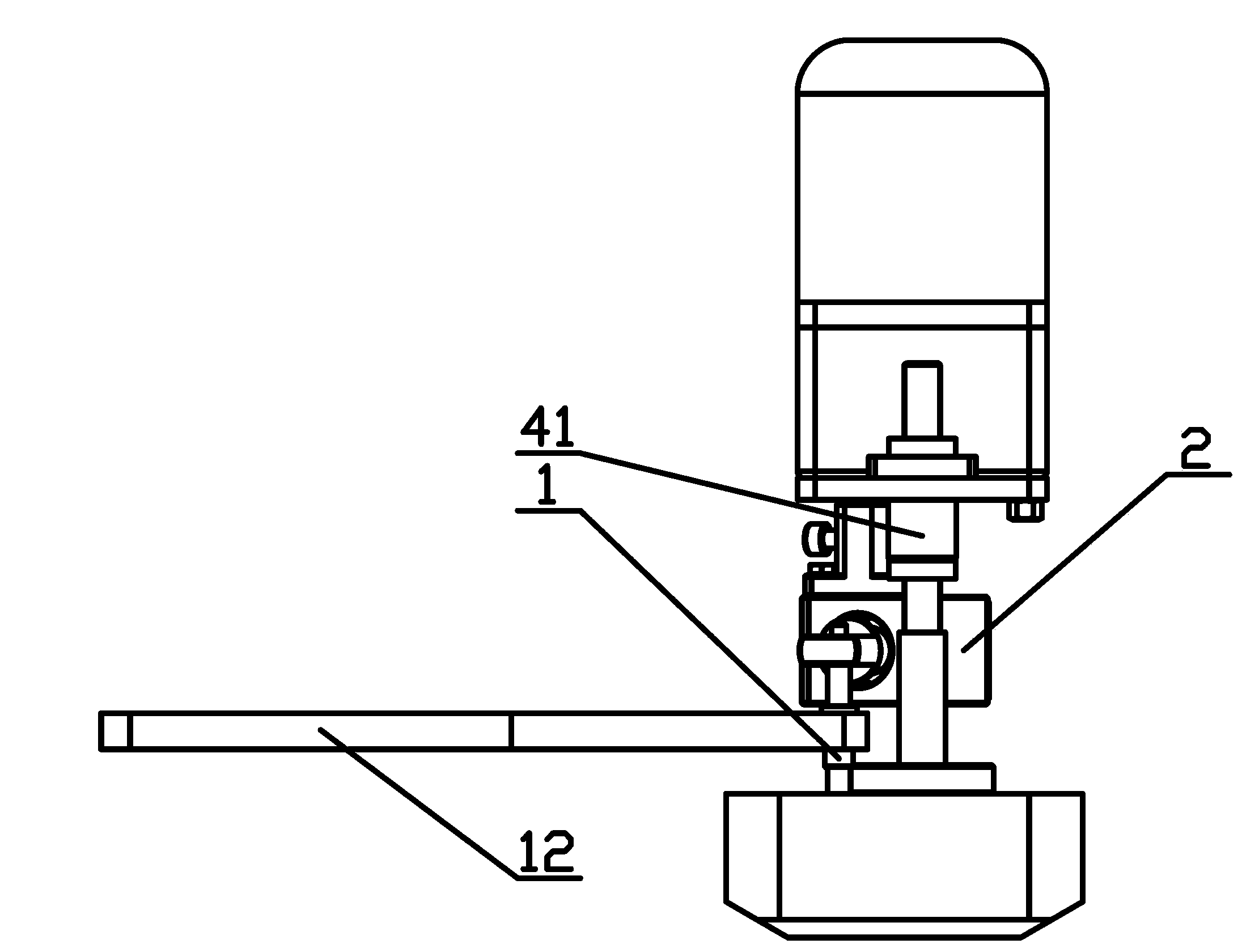
[0030] Adjustment of feed direction. The adjustment of the feed direction is realized through a transmission mechanism, which includes a guide mechanism 1 and a spring mechanism 2 .
[0031] Such as Figure 4 As shown, the spring mechanism 2 includes a spring guide rod 21, a guide rod bearing seat 22 adapted to the outer diameter of the spring guide rod 21, a bearing sleeve 23 fixed at one end of the spring guide rod 21, and a bearing sleeve 23 located between the guide rod bearing seat 22 and the spring guide rod 21. Spring 24 between bearing sleeves 23 .
[0032] The part o...
Embodiment 2
[0039] Embodiment 2, triangular hole processing.
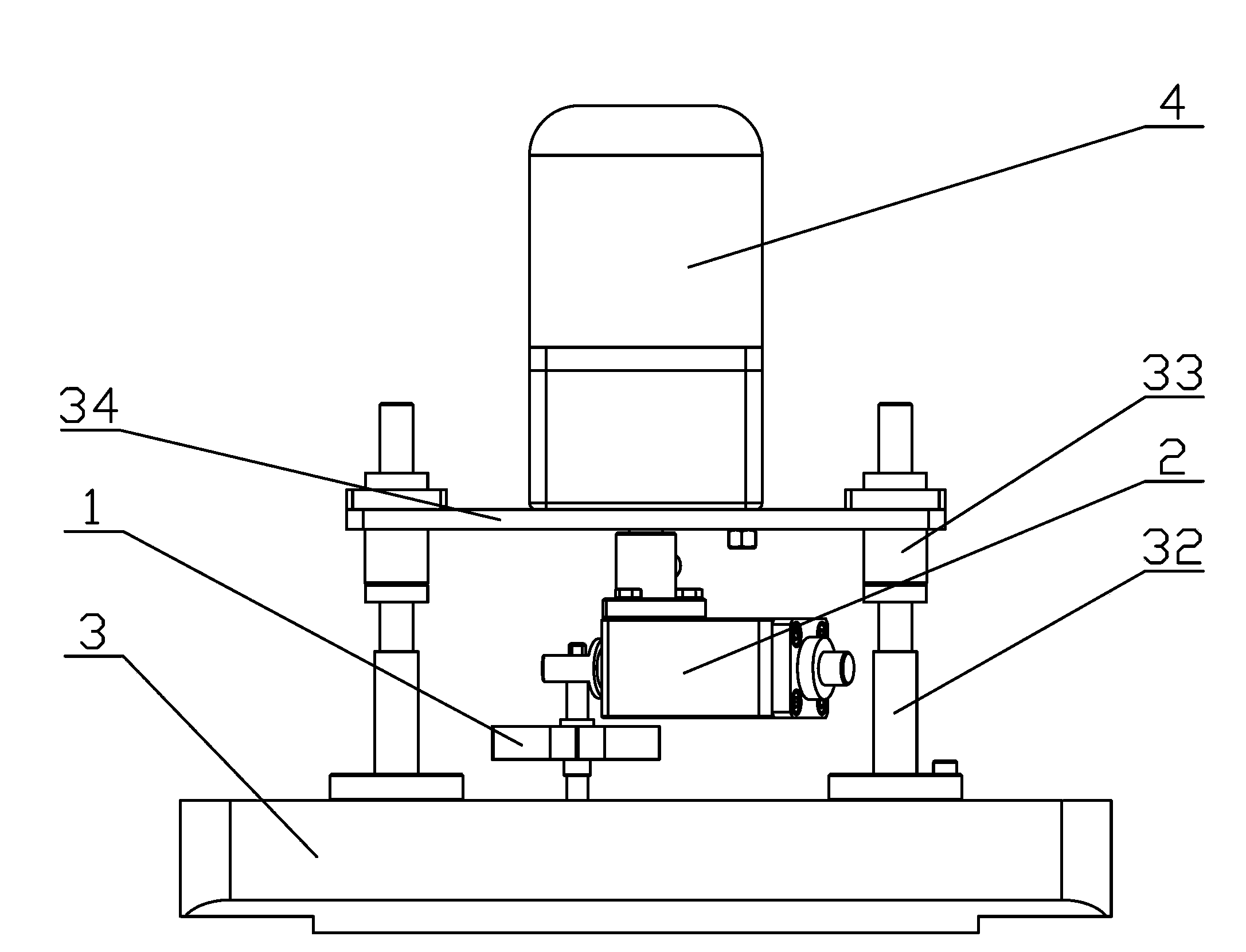
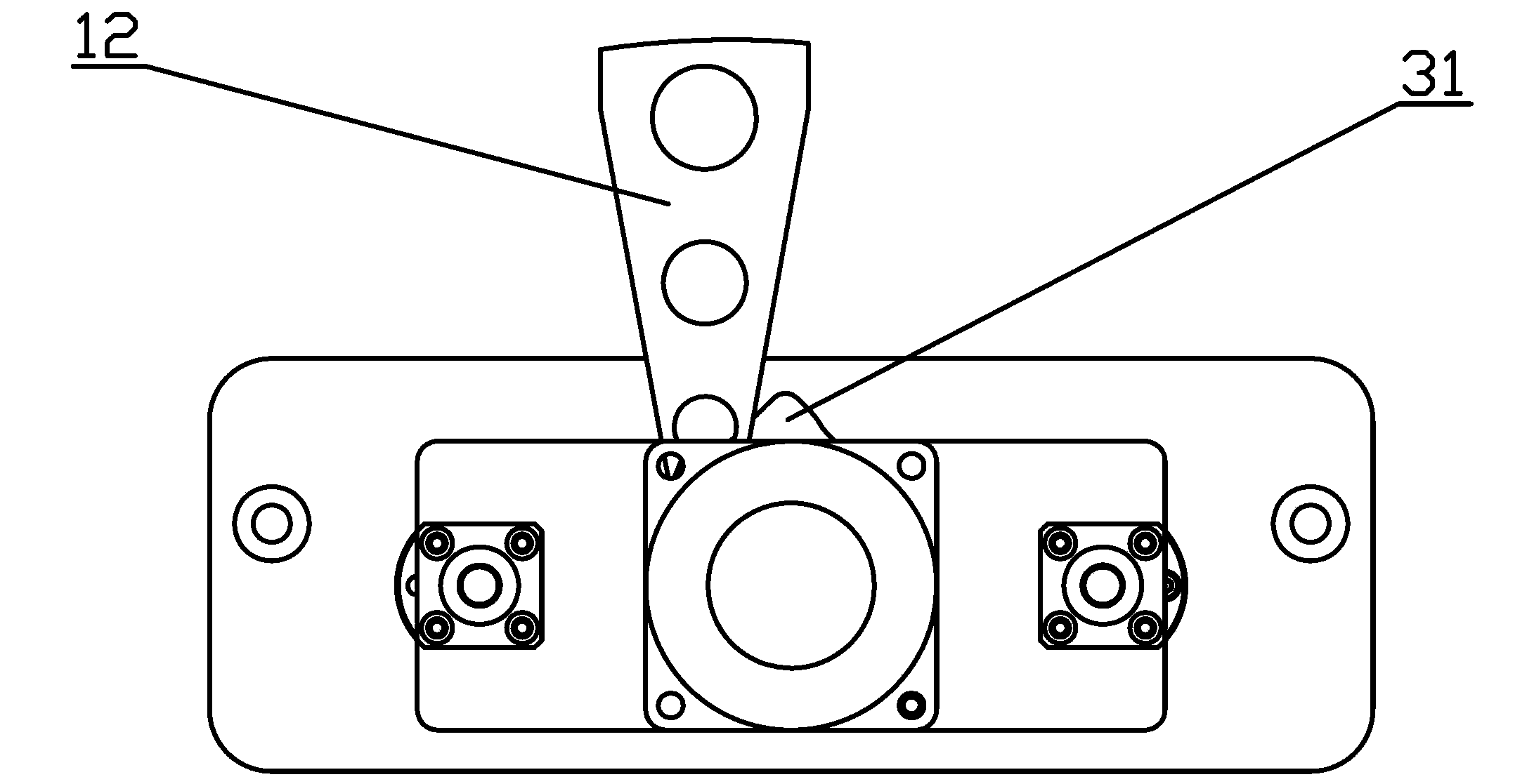
[0040] The transmission mechanism and power source in embodiment 2 are consistent with the transmission mechanism and power source in embodiment 1. The difference from Embodiment 1 is that the frame includes a base 3, an optical axis with seat 32 arranged on both sides of the guide hole, a linear bearing 33 and a fastening plate 34 arranged on both sides of the motor 4, and the base 3 is provided with a triangular Guide hole 31. At this time, the track of the tool movement on the guide plate 12 is consistent with the track of the guide shaft 11 moving along the wall of the triangular guide hole 31 , thereby realizing the machining of the triangular hole.
Embodiment 3
[0041]Embodiment 3, processing of holes of other shapes.
[0042] The transmission mechanism and power source in embodiment 3 are consistent with the transmission mechanism and power source in embodiment 1. The difference from Embodiment 1 is that the frame includes a base 3, an optical axis with seat 32 located on both sides of the guide hole, a linear bearing 33 and a fastening plate 34 located on both sides of the motor 4, and the base 3 is provided with other The shape of the guide hole 31, the contour generatrix of the guide hole 31 hole wall is a continuous and guideable curve, and the disturbance of this curve should be less than the disturbance of the guide shaft 11 cylindrical generatrix. At this time, the track of the tool movement on the guide plate 12 is consistent with the track of the guide shaft 11 moving along the wall of the guide hole 31 with other shapes. In addition, the inside of the guide hole 31 is required to be able to accommodate a circle with the mi...
PUM
 Abstract
Description
Claims
Application Information
 - R&D
- Intellectual Property
- Life Sciences
- Materials
- Tech Scout
- Unparalleled Data Quality
- Higher Quality Content
- 60% Fewer Hallucinations
Browse by: Latest US Patents, China's latest patents, Technical Efficacy Thesaurus, Application Domain, Technology Topic, Popular Technical Reports.
© 2025 PatSnap. All rights reserved.Legal|Privacy policy|Modern Slavery Act Transparency Statement|Sitemap|About US| Contact US: help@patsnap.com