Emergency parachuting device and method for multiple-rotor unmanned aerial vehicle

A multi-rotor unmanned aerial vehicle and unmanned aerial vehicle technology, which is applied in the field of agricultural unmanned aerial vehicle research, can solve the problems of reducing errors or even closing the throttle, the device is difficult to function in time, and it is difficult to effectively protect the aircraft, etc. Aircraft crash, light weight effect

Inactive Publication Date: 2014-07-02
SOUTH CHINA AGRI UNIV +1
View PDF5 Cites 83 Cited by
  • Summary
  • Abstract
  • Description
  • Claims
  • Application Information

AI Technical Summary

Problems solved by technology

However, for multi-rotor UAVs that do not have the ability to glide, there are two special situations: 1) The multi-rotor UAV has a power system failure during flight, loses lift, and falls rapidly
2) The operator mistakenly reduces or even closes the throttle during the manipulation of the multi-rotor UAV, causing the UAV to lose lift and fall rapidly
These two types of devices are difficult to play a role in time in the above situations
That is, the parachute device used for fixed-wing UAVs is difficult to effectively and timely enter the parachute state to protect the aircraft in unexpected situations unique to multi-rotor UAVs.

Method used


Image

  • Emergency parachuting device and method for multiple-rotor unmanned aerial vehicle
  • Emergency parachuting device and method for multiple-rotor unmanned aerial vehicle

Examples


Embodiment 1

[0035] In the prior art, UAV parachute devices are mostly used in fixed-wing aircraft. The first type is the manual trigger type, which requires the operator to issue a command to open the parachute when it is necessary to determine the landing; the second type is the out-of-control protection type. After the device detects that the remote control signal is lost, it enters the parachute procedure. However, for multi-rotor UAVs that do not have the ability to glide, the parachute device used for fixed-wing UAVs is difficult to effectively and timely enter the parachute state to protect the aircraft in emergencies unique to multi-rotor UAVs.

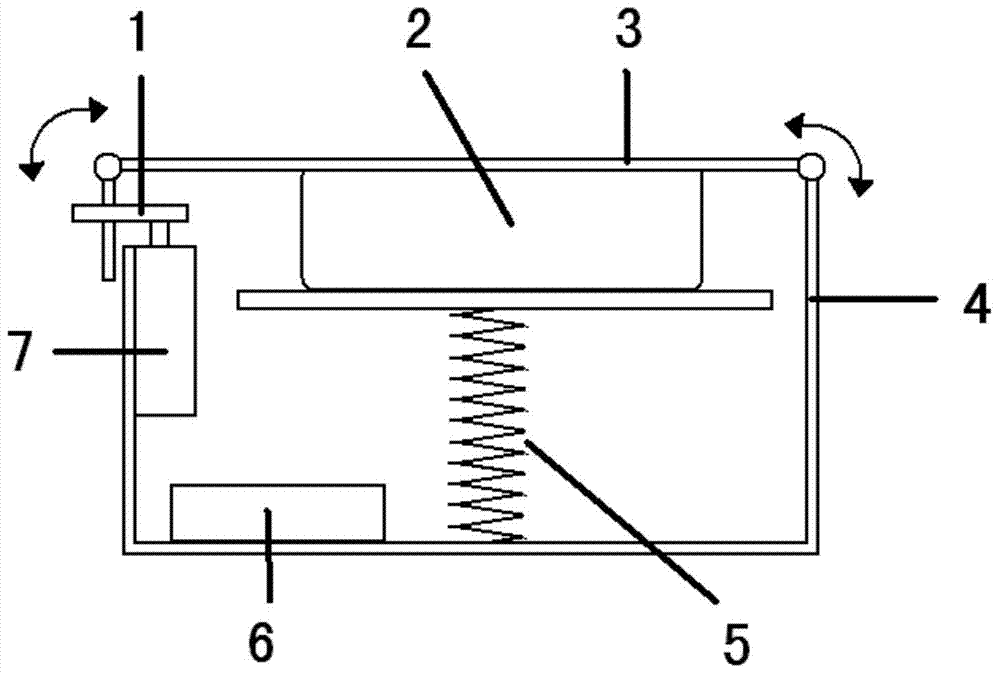
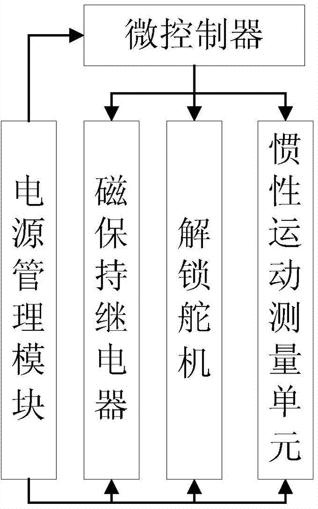
[0036] The emergency parachute device for multi-rotor UAV described in this embodiment, such as figure 1 and 2 As shown, it includes lock bolt 1, parachute 2, umbrella compartment cover 3, umbrella compartment 4, parachute throwing spring 5, measurement and control unit (including built-in lithium battery) 6, and unlocking steering gear 7...


PUM


Abstract

The invention discloses an emergency parachuting device and method for a multiple-rotor unmanned aerial vehicle. The device comprises a measurement and control unit, an unlocking steering engine, a parachute-throwing spring, a latch, a parachute and a magnetic latching relay, wherein the measurement and control unit, the unlocking steering engine, the parachute-throwing spring, the latch, the parachute and the magnetic latching relay are installed in a parachute bin. The measurement and control unit comprises a microcontroller and an inertia movement measurement unit, wherein the microcontroller is electrically connected with the unlocking steering engine and the magnetic latching relay; the unlocking steering engine is connected with the latch through a rocker arm, and the magnetic latching relay is used for connecting or disconnecting a power supply of a rotor motor; the parachute bin is fixed to the multiple-rotor unmanned aerial vehicle, one end of the parachute-throwing spring is fixed to the bottom of the parachute bin, and the parachute is arranged at the other end of the parachute-throwing spring. The method includes the following steps that the current instant height and acceleration of the unmanned aerial vehicle are acquired, the dropping rate of the unmanned aerial vehicle is worked out, whether the unmanned aerial vehicle flies under a dangerous dropping state or not is judged, and if yes, the power supply of the rotor motor is disconnected, and the parachute is thrown out to make the unmanned aerial vehicle safely land. The emergency parachuting device has the advantages of being simple in structure, low in cost, light in weight, high in reaction speed and the like.

Description

technical field [0001] The invention relates to the field of research on agricultural unmanned aerial vehicles, in particular to an emergency parachute device and method for multi-rotor unmanned aerial vehicles. Background technique [0002] The multi-rotor light and small UAV has the characteristics of small size and rapid attitude response, which is convenient for rapid deployment and use in orchards with complex terrain. In the field of practical agricultural applications, drones can carry various operating equipment to carry out rapid agricultural situation collection and precise operations in agricultural areas, which can greatly reduce labor costs and improve the utilization rate of pesticides. [0003] At present, UAV parachute devices are mostly used in fixed-wing aircraft. The first type is manually triggered, and the operator needs to issue a command to open the parachute when he determines that he needs to land; the second type is out of control protection. After...

Claims


Application Information

Patent Timeline
IPC IPC(8): B64D45/04B64D17/80B64D17/54
Inventor 徐兴徐胜刘永鑫岳学军周志艳蔡坤胡洁李继宇王叶夫全东平燕英伟
Owner SOUTH CHINA AGRI UNIV
Why Eureka
Try Eureka