Laser shock peening method of blisk
A technology of laser shock strengthening and integral blisk, applied in the field of integral blisk laser shock strengthening, can solve the problems of the influence of surface roughness and size, the difficulty of implementing irregular surface parts, the deformation of thin-walled parts, etc. High frequency vibration fatigue life improvement and high efficiency
- Summary
- Abstract
- Description
- Claims
- Application Information
AI Technical Summary
Problems solved by technology
Method used
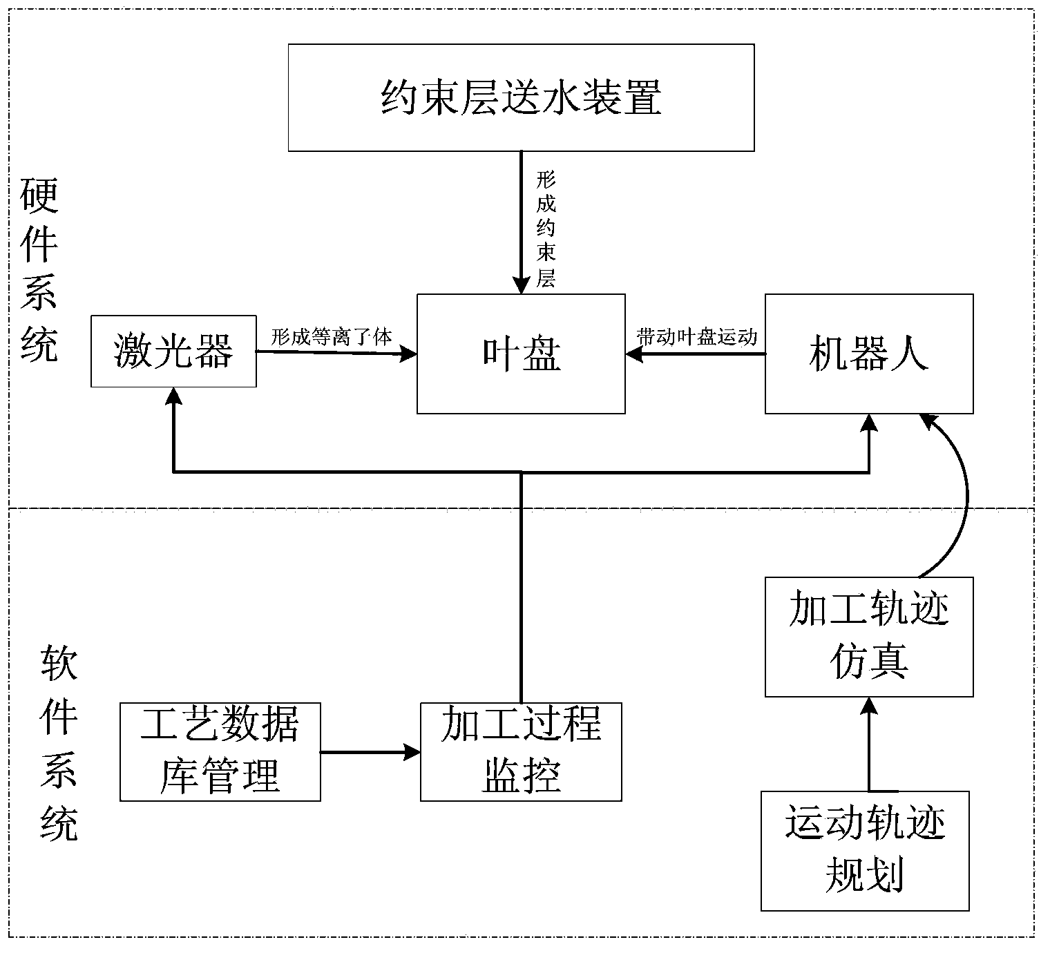
Image

Examples
Embodiment 1
[0203] Specimen material: TC17 titanium alloy blisk.
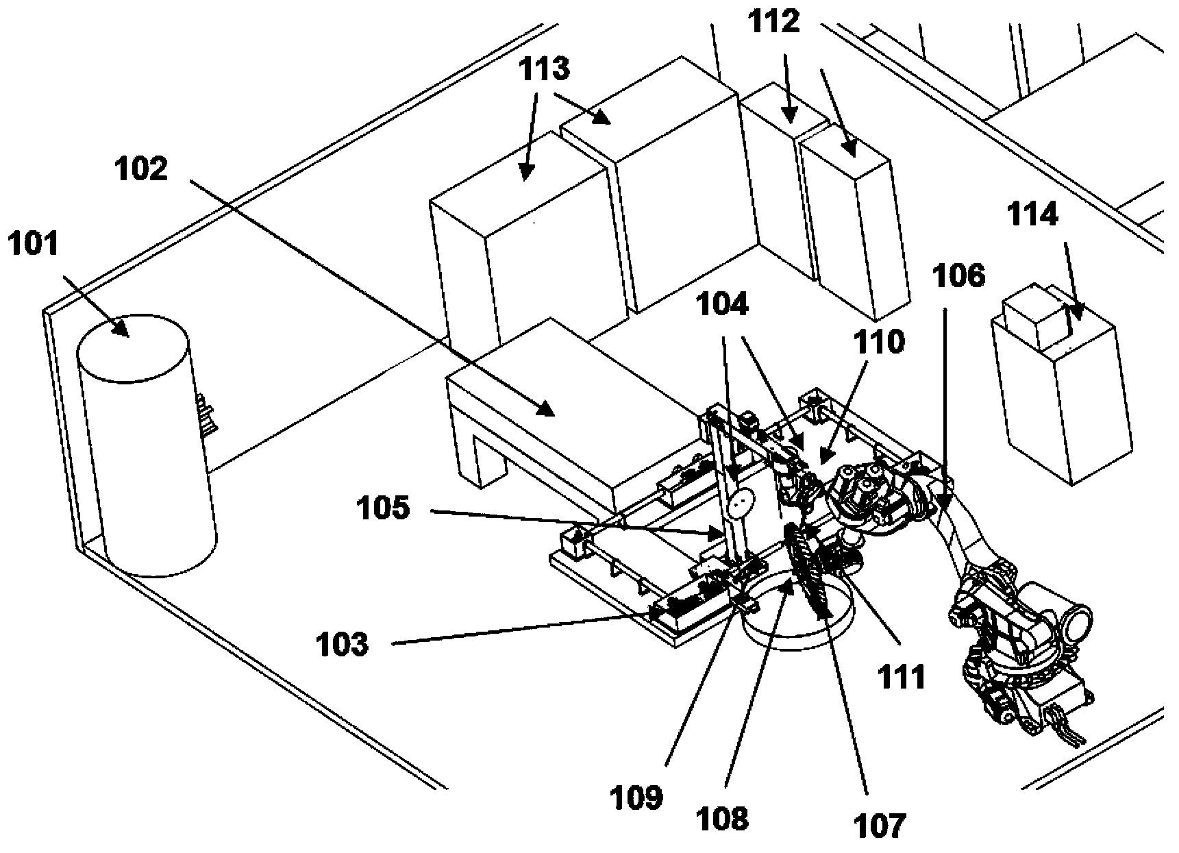
[0204] Pretreatment of the workpiece: first clean it with acetone to remove the oil on the surface, and then put it in the air shower for 5 minutes to remove the dust on the surface of the leaf disc (13).
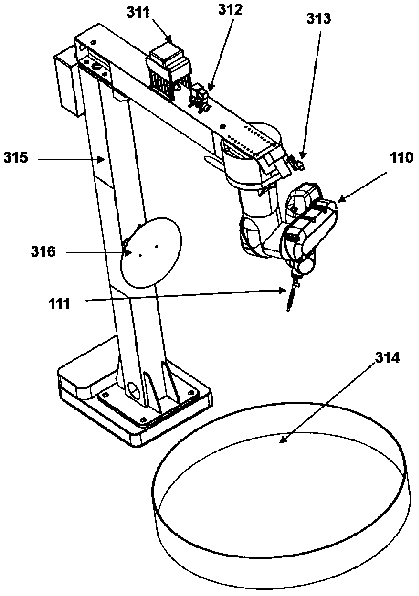
[0205] Laser shock strengthening process parameters: ①The constrained layer uses deionized water, the resistivity of deionized water reaches 18 trillion, the thickness of the constrained layer is 1mm, and the thickness is uniform; ②The left focusing optical path and the right focusing optical path output a single pulse energy of 6J, The pulse width is 15ns, the diameter of the circular spot is 3mm, the left and right uniform light paths output a single pulse energy of 7J, the pulse width is 15ns, and the side length of the square spot is 3mm; the overlapping rate of the circular spot is 30%, and the square spot The overlap rate is 15%.
Embodiment 2
[0207] Pretreatment of the workpiece: first clean it with acetone to remove the oil on the surface, and then put it in the air shower for 5 minutes to remove the dust on the surface of the leaf disc (13).
[0208] Laser shock strengthening process parameters: ① The constrained layer uses deionized water, the resistivity of deionized water reaches 18 trillion, the thickness of the constrained layer is 2 mm, and the thickness is uniform; ② The left and right focus optical paths output single pulse energy of 10J, The pulse width is 120ns, the diameter of the circular spot is 3mm, the left and right uniform light paths output a single pulse energy of 10J, the pulse width is 20ns, and the side length of the square spot is 3mm; the overlapping rate of the circular spot is 20%, and the square spot The overlap rate is 5%.
Embodiment 3
[0210] Pretreatment of the workpiece: first clean it with acetone to remove the oil on the surface, and then put it in the air shower for 5 minutes to remove the dust on the surface of the leaf disc (13).
[0211] Laser shock strengthening process parameters: ① The constrained layer uses deionized water, the resistivity of deionized water reaches 18 trillion, the thickness of the constrained layer is 1.5mm, and the thickness is uniform; ② The left and right focus optical paths output a single pulse energy of 8J , pulse width 18ns, diameter of circular spot is 3mm, left uniform light path and right uniform light path output single pulse energy 9J, pulse width 17ns, square spot side length is 3mm; circular spot overlap rate is 24%, square The overlapping rate of the spot is 8%.
[0212] The mechanical properties before and after laser shock peening of the overall blisks of the above-mentioned Examples 1-3 are shown in Table 1.
[0213] Table 1 Mechanical properties of the whole...
PUM
| Property | Measurement | Unit |
|---|---|---|
| thickness | aaaaa | aaaaa |
| width | aaaaa | aaaaa |
| thickness | aaaaa | aaaaa |
Abstract
Description
Claims
Application Information
 - R&D
- Intellectual Property
- Life Sciences
- Materials
- Tech Scout
- Unparalleled Data Quality
- Higher Quality Content
- 60% Fewer Hallucinations
Browse by: Latest US Patents, China's latest patents, Technical Efficacy Thesaurus, Application Domain, Technology Topic, Popular Technical Reports.
© 2025 PatSnap. All rights reserved.Legal|Privacy policy|Modern Slavery Act Transparency Statement|Sitemap|About US| Contact US: help@patsnap.com