
Maximum power point tracking method for wind power generation system based on Boost convertor

A technology of wind power generation system and maximum power point, which is applied in the direction of wind power generation, wind engine, wind engine control, etc., can solve the problems of increasing actual cost, reducing wind energy conversion efficiency, and slow response speed, so as to improve power quality and reduce Application cost, effect of suppressing power disturbance

Inactive Publication Date: 2014-07-02
上海中认尚科新能源技术有限公司
View PDF5 Cites 9 Cited by
  • Summary
  • Abstract
  • Description
  • Claims
  • Application Information

AI Technical Summary

Problems solved by technology

These three methods have their own shortcomings: the tip speed ratio method needs to use mechanical sensors to measure the wind speed and the speed of the wind rotor, and also needs to know the inherent tip speed ratio curve of the wind turbine
The first two increase the actual cost of the system, and the actual curve of the fan characteristic curve will deviate from the original curve after the fan is used for a long time, making the wind energy MPPT tracking inaccurate
The hill-climbing search method does not need to measure the wind speed or speed, nor does it need to know the specific power characteristics of the wind turbine. It uses a fixed speed disturbance to maximize the wind energy capture of the wind turbine. However, this method uses a fixed disturbance step during tracking, and the disturbance step is too small , the response speed is slow, which reduces the rapidity of tracking; when the disturbance step is too large, the power oscillates near the maximum power point, resulting in a large difference between the tracked maximum power point and the actual value, which reduces the wind energy conversion efficiency

Method used


Image

  • Maximum power point tracking method for wind power generation system based on Boost convertor
  • Maximum power point tracking method for wind power generation system based on Boost convertor
  • Maximum power point tracking method for wind power generation system based on Boost convertor

Examples


Embodiment 1

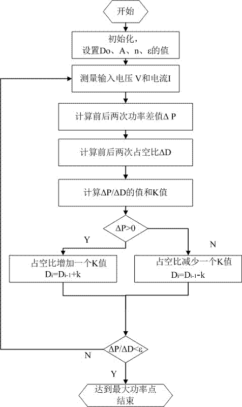
[0017] see figure 1 , the present embodiment is based on the method for tracking the maximum power point of a wind power generation system with a Boost type converter, which is characterized in that in the Boost type converter circuit, the output power of the generator is controlled by changing the circuit duty ratio, and the specific operation steps are as follows:

[0018] a. System initialization, set tracking error , respectively measure the input voltage and current of the Boost converter circuit twice before and after the sampling period, calculate the input power, and calculate the power difference between the two times before and after?P;

[0019] b. Obtain the duty cycle of the converter at the two sampling times from the controller MCU, and calculate the duty cycle difference ?D;

[0020] c. Determine the change direction of the duty cycle according to the positive or negative of the power difference ?P. If ?P>0, the duty cycle increases by one tracking st...

Embodiment 2

[0022] Embodiment 2: This embodiment is basically the same as Embodiment 1, and the special feature is: the variable step size variation K is:

[0023]

[0024] In the formula: the step size variation K, D is the circuit duty cycle, A is the step size disturbance factor, n is the step size attenuation factor, e is the natural logarithm, the power difference between the two samples before and after? P, the two samples before and after Duty cycle difference?D.

Embodiment 3

[0026] This embodiment is based on the maximum power point tracking method of the wind power generation system based on the Boost converter, and its theoretical basis is as follows:

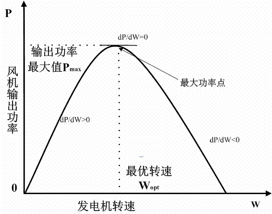
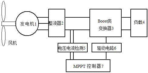
[0027] When the wind turbine system operates at the maximum power point, the power generation system such as figure 2 As shown, the relationship between fan power and fan speed is as follows:

[0028] (1)

[0029] Expand to get:

[0030] (2)

[0031] In the formula: - fans capture power, - Fan mechanical angular velocity, D-Boost circuit duty cycle, -Boost circuit input voltage, - Generator phase voltage angular velocity.

[0032] In a Boost circuit, the input voltage and output voltage The following relationship exists:

[0033] (3)

[0034] (4)

[0035] The relationship between the mechanical angular velocity of the fan and the angular velocity of the phase voltage of the generator is as follows:

[0036] (5)

[...


PUM


Abstract

The invention provides a maximum power point tracking method for a wind power generation system based on a Boost convertor. The method concretely includes the following steps that a, a system is initialized, a tracking error is set, input voltages and input currents of the convertor before and after a sampling period are measured, and the difference delta P between the power before the sampling period and the power after the sampling period is calculated; b, the difference delta D between the duty ratios of the convertor before and after sampling is calculated; c, if delta P is larger than zero, the duty ratio is increased by a tracking step size variable quantity K, and if delta P is smaller than zero, the duty ratio is reduced by K; d, the quotient of delta P to delta D is calculated, and if an end condition is met, the system reaches the maximum power point; if the end condition is not met, the step a is executed, and the steps are repeated until the end condition is met. According to the method, wind speed or fan rotating speed is measured without depending on a mechanical measuring device, the tracking speed, stability and accuracy of the system are effectively improved by using a variable-step-size duty ratio disturbance tracking algorithm, and not only can output efficiency and electric energy quality be improved, but also complexity and cost of the system are reduced.

Description

technical field [0001] The invention relates to the technical field of automatic control of wind power generation, and relates to a method for tracking the maximum power point of a wind power generation system based on a Boost converter. Background technique [0002] Today, when sustainable development is advocated, wind energy, as a clean and renewable energy source, has received extensive attention. China has abundant wind energy resources, the total reserves of wind energy resources are about 160,000 MW, but wind energy has the characteristics of low energy density, randomness, and instability. In order to make full use of wind energy at different wind speeds and maximize the conversion of wind power generation systems To improve efficiency, measures must be taken to control the output power of the generator to ensure that the wind turbine always works at the maximum power point and maximize the utilization of wind energy. [0003] At present, the conventional ma...

Claims


Application Information

Patent Timeline
Patent Type & Authority Applications(China)
IPC IPC(8): F03D7/00
CPCY02E10/723Y02E10/72
Inventor 谢少荣李梦赵重阳李恒宇罗均
Owner 上海中认尚科新能源技术有限公司
Learn More