Isolated axial flow pump blade

An axial flow pump, independent technology, applied in the field of independent axial flow pump blades, can solve the problems of impeller material not fully applicable, too many corrosive substances, etc.

Inactive Publication Date: 2014-07-02
安徽华瑞塑业有限公司
View PDF11 Cites 3 Cited by
  • Summary
  • Abstract
  • Description
  • Claims
  • Application Information

AI Technical Summary

Problems solved by technology

It achieves the function of transporting liquid. When the liquid passes through the impeller, the pressure increases due to the rotation of the impeller. The function of the axial flow pump is to convert the kinetic energy of the fluid into pressure energy through the rotating impeller. In this process, the strength of the blade is compared. At the same time, some seriously polluted water contains a lot of corrosive substances, and the existing impeller materials are no longer fully applicable.

Method used


Image

  • Isolated axial flow pump blade
  • Isolated axial flow pump blade

Examples


Embodiment Construction

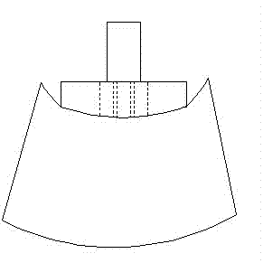
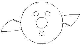
[0019] See the attached figure, the independent axial flow pump blade, the main body of the blade is a disc-shaped connecting part, one side of the disc is a spiral blade structure, and the other side is a cylindrical shaft structure, the blade body is made of injection molding, and the material is thermosetting resin nano Composite material, the outer surface of the blade main body is covered with ultra-high molecular weight polyethylene coating; the side connecting the disc connecting part and the spiral blade is arc-shaped; the connecting part of the disc is connected concentrically with the cylinder shaft; There is an adhesive layer between the coatings through frosting treatment; the ultra-high molecular weight polyethylene coating is: ultra-high molecular weight polyethylene UHMWPE LS4140, ultra-high molecular weight polyethylene UHMWPE L3000, Japan Mitsui Chemicals ultra-high molecular weight polyethylene UHMWPE L4000, ultra-high molecular weight polyethylene High molecu...


PUM


Abstract

The invention discloses an isolated axial flow pump blade which comprises a blade body. The isolated axial flow pump blade is characterized in that the blade body is a disc-shaped connection part, one face of a disc is of a spiral blade structure and the other face of the disc is of a cylinder axis structure. The blade body is formed in an injection molding mode and made of thermosetting resin nanocomposite. The outer face of the blade body is coated with an ultra high molecular weight polyethylene layer. The shortcomings of the prior art are overcome, the designed structure is reasonable, the blade and an impeller shaft can be detached, the number of blades is freely chosen, and the material is the nanometer polymer composite material which is resistant to corrosion and high in weather fastness. The isolated axial flow pump blade is not prone to corrosion, and capable of ensuring the good working performance, prolonging the service life and greatly reducing fees in maintaining and replacing the blade of the impeller.

Description

[0001] technical field [0002] The invention relates to the technical field of axial flow pump blades, in particular to independent axial flow pump blades. [0003] Background technique [0004] The axial flow pump is composed of the main parts such as the pump casing, the impeller and the shaft. The new liquid is sucked from the other end, and the liquid generates a continuous flow along the direction parallel to the rotating shaft. It achieves the function of transporting liquid. When the liquid passes through the impeller, the pressure increases due to the rotation of the impeller. The function of the axial flow pump is to convert the kinetic energy of the fluid into pressure energy through the rotating impeller. In this process, the strength of the blade is compared. At the same time, some seriously polluted water contains more corrosive substances, and the existing impeller materials cannot be fully applied. [0005] Contents of the invention [0006] The purpose...

Claims


Application Information

Patent Timeline
IPC IPC(8): F04D29/18F04D29/02
Inventor 汪政
Owner 安徽华瑞塑业有限公司
Why Eureka
Try Eureka