Imaging spectrometer beam splitting system based on free-form surface

An imaging spectrometer and spectroscopic system technology, which is applied in the directions of spectrometry/spectrophotometry/monochromator, instruments, scientific instruments, etc. and other problems to achieve the effect of improving imaging quality, simplifying design and reducing volume

Inactive Publication Date: 2014-07-02
SHANGHAI INST OF TECHNICAL PHYSICS - CHINESE ACAD OF SCI
View PDF16 Cites 11 Cited by
  • Summary
  • Abstract
  • Description
  • Claims
  • Application Information

AI Technical Summary

Problems solved by technology

However, compared with convex gratings and concave gratings, the Czerny-Turner structure using planar gratings is limited by aberration correction, and it is difficult to achieve a large relative aperture, and the chromatic distortion and spectral line bending caused by the lengthening of the slit also decrease. Rapid growth, poor aberration correction ability and low resolution
In order to make up for these defects and correct various aberrations, the Czerny-Turner structure based on planar gratings is often used in spectral imaging systems with small aberrations and large F numbers, and in order to increase the freedom of balancing aberrations, each component often has different degrees of Rotation and eccentricity, high requirements for design and assembly, long development cycle
[0

Method used


Image

  • Imaging spectrometer beam splitting system based on free-form surface
  • Imaging spectrometer beam splitting system based on free-form surface
  • Imaging spectrometer beam splitting system based on free-form surface

Examples


Embodiment Construction

[0024] Below in conjunction with accompanying drawing and embodiment the present invention is described in further detail:

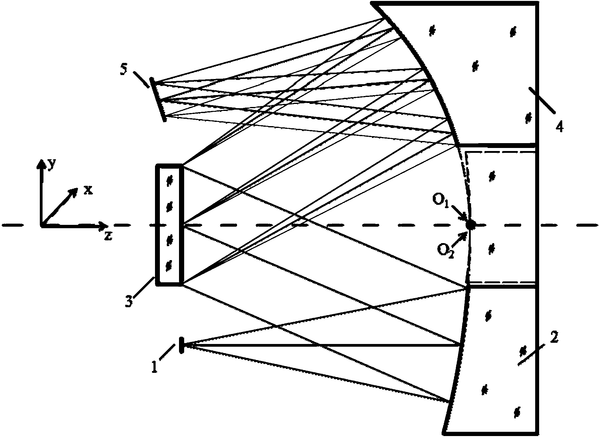
[0025] Such as figure 1 As shown, the spectrometer light-splitting system of the present invention takes the high-performance, simple-structured convex grating Offner structure and the Czerny-Turner structure based on the planar grating as design prototypes, takes the advantages of the two, avoids its shortcomings, and realizes in components and structures High-performance light splitting under the premise of simplicity. The spectroscopic system includes a slit 1 , a collimating free-form surface mirror 2 , a diffraction grating 3 , an imaging free-form surface mirror 4 and an image plane detector 5 . The slit 1 is the focal plane of the front telescopic objective lens, and the incident beam from a distant target is imaged on the slit through the telescope, which is used as the object plane of the spectroscopic system; the collimating free-form surface ...


PUM


Abstract

The invention discloses an imaging spectrometer beam splitting system based on a free-form surface. The system is composed of an entrance slit, a free-form surface collimation reflector, a plane diffraction grating, a free-form surface imaging reflector and an image surface detector. The imaging spectrometer beam splitting system is characterized in that the high-freedom-degree non-rotation-symmetrical free-form surface is used in cooperation with the plane grating which is high in performance and mature in technology, and the beam splitting system which is simple and compact in structure, low in aberration, low in distortion and high in efficiency is realized. In the system, the mode that the hole diameter deviates from the axis is adopted to achieve the purpose of no light obstruction, relative angle rotation does not exist among all optical elements, installation and adjustment can be realized conveniently and easily, and the development time can be shortened. The beam splitting system based on the free-form surface realizes good spectral imaging at the 8-12.5-micrometer long wave infrared spectrum, and on the premise that it is guaranteed that the system is simple and compact, spherical aberration, comatic aberration, astigmatism, spectral distortion, spectral line bending and the like are well corrected. The imaging spectrometer beam splitting system can be applied to the field of aerospace and aviation hyperspectral imaging.

Description

technical field [0001] The present invention belongs to the field of imaging spectrometer design, and specifically relates to a novel optical design of a plane grating spectroscopic system based on a free-form surface. The spectral band of the embodiment of the present invention is long-wave infrared, and it is also applicable to other fields such as visible near-infrared or mid-wave infrared. Design of spectroscopic components for spectral imaging systems with spectral bands. Background technique [0002] Imaging spectrometer is an organic combination of imaging technology and spectral technology. It can simultaneously obtain two-dimensional spatial information and one-dimensional spectral information of the target to form a data cube, which is widely used in social production, military activities, space and astronomical exploration, and aerospace. remote sensing and many other fields. Its optical system is generally composed of a pre-telescope system and a spectral spectr...

Claims


Application Information

Patent Timeline
IPC IPC(8): G01J3/02
Inventor 侯佳何志平袁立银况耀武舒嵘
Owner SHANGHAI INST OF TECHNICAL PHYSICS - CHINESE ACAD OF SCI
Why Eureka
Try Eureka