Opening and closing induction current vacuum switch device

A technology of vacuum switch and inductive current, applied in electrical switches, high-voltage/high-current switches, circuits, etc., can solve the problem that the operation performance of the instantaneous switch of the vacuum switch part cannot be satisfied, the quick performance and reliability of the switch operation are affected, and the assembly and coordination structure is complex. and other problems, to achieve the effect of improving the instantaneousness of the switch drive, reducing the structural links and simplifying the operating mechanism

Active Publication Date: 2014-07-02
LIAONING YIDE IND GRP CO LTD
View PDF5 Cites 3 Cited by
  • Summary
  • Abstract
  • Description
  • Claims
  • Application Information

AI Technical Summary

Problems solved by technology

The "opening and closing induction current vacuum switch" disclosed by the Chinese patent (patent number is CN2006100472737), its operating mechanism is the core that converts the counterclockwise and clockwise switch rotation into the longitudinal switching action of the vacuum switch part, and its composition includes sector teeth meshing The technical scheme of the transmission part, cam part, swing plate mechanism, sickle mechanism and chuck part adopts a single cam to drive the swing plate, sickle plate and connecting plate, and drives the lower contact rod of the vacuum switch part to move longitudinally to realize the switch operation. , the mechanism consists of many links and the assembly and coordination structure is complex, which affects the quick performance and reliability of its switch operation. Another key technical problem is that the switch action stroke of the vacuum switch part only comes from the single cam protrusion stroke, which cannot meet the requirements of vacuum. Momentary switch operation performance of the switch part

Method used


Image

  • Opening and closing induction current vacuum switch device
  • Opening and closing induction current vacuum switch device
  • Opening and closing induction current vacuum switch device

Examples


Embodiment Construction

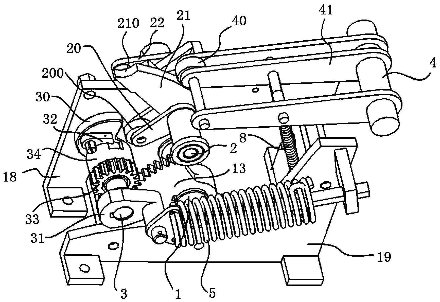
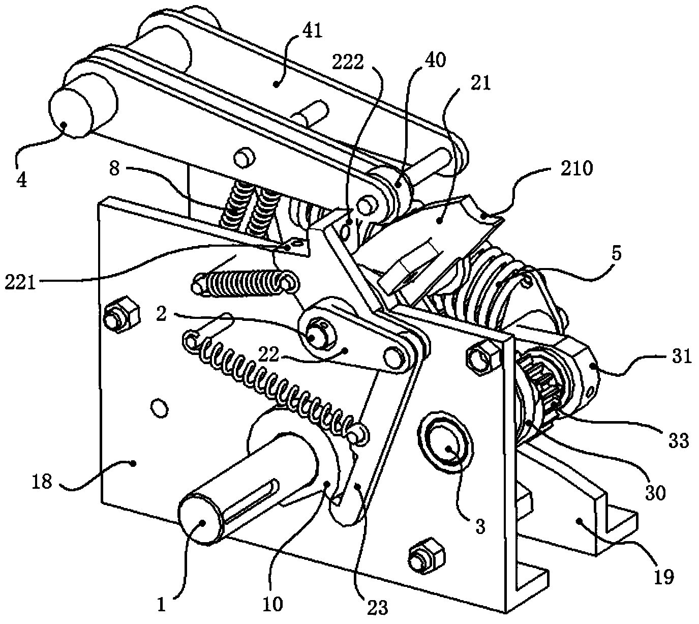
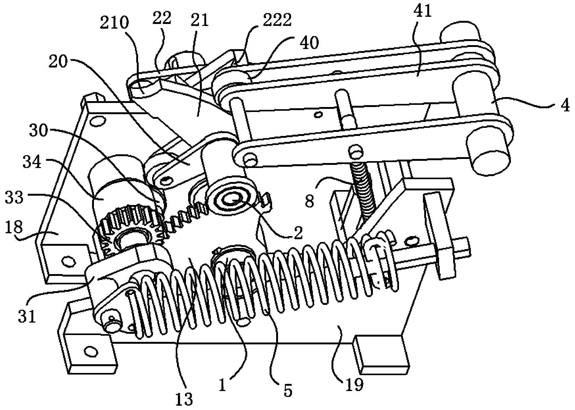
[0011] The opening and closing induction current vacuum switch device proposed in the patent application of the present invention is composed of a vacuum switch part and a control box at the lower part of the vacuum switch part, and the vacuum switch is arranged in an insulating sleeve. Since the technical features of the technical solution of the present application do not involve the structure of the upper vacuum switch part, only the components in the control box and the process of realizing the action are shown.

[0012] The mounting plate in the control box body is actually two parallel mounting splints 18, 19 in this embodiment, and the rotation support between the two mounting splints 18, 19 is provided with parallel manipulation shaft 1, main shaft 3, drive shaft 2 and gate The movable arm shaft 4, the brake arm 41 on the brake arm shaft 4 is used as the switch operating part for driving the lower contact rod of the vacuum switch to pull down and open and push up to clo...


PUM


Abstract

The invention provides an opening and closing induction current vacuum switch device. The opening and closing induction current vacuum switch device is composed of a vacuum switch part and a control case at the lower portion of the vacuum switch part, wherein the vacuum switch part is arranged in an insulation sleeve; an operating shaft, a main shaft, a drive shaft and a brake crank arm shaft are arranged on an installation board inside the case body of the control case; a brake crank arm drives a lower contact feeler lever of the vacuum switch part; a round gear of the main shaft is in meshed transmission with a sector gear of the operating shaft; a cam of the main shaft is matched with a roller crankshaft fixed to the drive shaft; a sector plate guides the brake crank arm to swing vertically in a reciprocating mode. Compared with the prior art, the opening and closing induction current vacuum switch device has the advantages that the structure is simplified, switch drive instantaneity of the controlled vacuum switch part is largely improved, and safe and reliable operation of a high-voltage grid is guaranteed.

Description

technical field [0001] The patent application of the present invention relates to a transfer current device for high-voltage, ultra-high voltage and ultra-high voltage switching of high-voltage, ultra-high-voltage and ultra-high-voltage switching of outdoor AC high-voltage isolating switches that cooperate with 110-1100KV outdoor high-voltage isolating switches to realize arc-free breaking of outdoor AC high-voltage isolating switches and achieve busbar switching load current operations. Background technique [0002] In the technical field, the transfer current device is connected with the secondary contact and the main contact of the grounding switch or the disconnector with the grounding device, and the auxiliary contact and the main contact are opened and closed through their own vacuum switch contacts. Inductive high voltage, to achieve the technical purpose of secondary contact, main contact switching action without high-voltage arc flash, to ensure the safe operation of...

Claims


Application Information

Patent Timeline
IPC IPC(8): H01H33/66H01H33/666
Inventor 钟启辉杜玉乐杜玉园于鹤田丛俊王治财蔡立荣王彬
Owner LIAONING YIDE IND GRP CO LTD
Why Eureka
Try Eureka