An organic electroluminescent device with a barrier layer

An electroluminescent device and barrier layer technology, applied in the direction of electro-solid devices, electrical components, circuits, etc., can solve the problems of triplet energy level mismatch and low luminous efficiency, achieve excellent luminous efficiency, ensure luminous efficiency, and easily selected effect

Active Publication Date: 2016-05-25
GUAN YEOLIGHT TECH CO LTD +1
View PDF4 Cites 0 Cited by
  • Summary
  • Abstract
  • Description
  • Claims
  • Application Information

AI Technical Summary

Problems solved by technology

[0009] For this reason, the technical problem to be solved by the present invention is that in the prior art, the triplet energy level mismatch easily occurs between the blue fluorescent light-emitting layer and the red-green phosphorescent light-emitting layer, resulting in low luminous efficiency. Barrier layers for electroluminescent devices;

Method used


Image

  • An organic electroluminescent device with a barrier layer
  • An organic electroluminescent device with a barrier layer
  • An organic electroluminescent device with a barrier layer

Examples


Embodiment 1

[0116] Organic electroluminescent device structure:

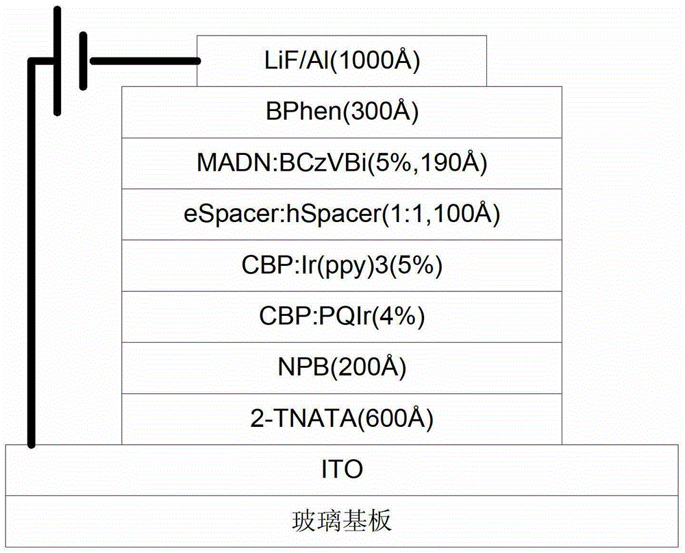
[0117] ITO / 2-TNATA(60nm) / NPB(20nm) / EMLR / EMLG-1 / Spacer(10nm) / EML-B / BPhen(30nm) / LiF(3nm) / Al(150nm)

[0118] like image 3 As shown, it is a cross-sectional view of the structure of Embodiment 1 of the present invention, which includes a substrate 10, an anode layer 20, a hole injection layer 30, a hole transport layer 40, a red phosphorescent light-emitting layer 50, a green phosphorescent light-emitting layer 60, and a blocking layer. 70 , blue fluorescent light-emitting layer 80 , electron transport layer 90 , cathode layer 100 .

[0119] The preparation method of the organic light-emitting device is as follows:

[0120] ①Using detergent ultrasonic and deionized water ultrasonic methods to clean the ITO glass substrate that has been etched with a fixed pattern, and place it to dry under an infrared lamp.

[0121] ②Place the above-treated glass substrate in a vacuum chamber and evacuate to 1×10 -5 Pa, a hole injection la...

Embodiment 2

[0132] Organic electroluminescent device structure:

[0133] ITO / 2-TNATA(60nm) / NPB(20nm) / EML-R / EMLG-2 / Spacer(10nm) / EML-B / BPhen(30nm) / LiF(3nm) / Al(150nm)

[0134] The preparation method is the same as that in Example 1, except that the green phosphorescent light-emitting layer material in step ④ is replaced.

Embodiment 3

[0136] Organic electroluminescent device structure:

[0137] ITO / 2-TNATA(60nm) / NPB(20nm) / EML-B / Spacer(10nm) / EMLG-1 / EMLR / BPhen(30nm) / LiF(3nm) / Al(150nm)

[0138] The preparation method is the same as that in Example 1, except that step ④ is implemented after step ⑥, and the evaporation sequence of the green phosphorescent light-emitting layer is reversed with that of the red phosphorescent light-emitting layer.


PUM


Abstract

The invention relates to a barrier layer and an organic electroluminescent device with the barrier layer, comprising a substrate, and an anode layer, a light-emitting unit layer and a cathode layer sequentially formed on the substrate; the light-emitting unit layer includes holes Injection layer, hole transport layer, light emitting layer, electron transport layer, the hole injection layer is formed on the anode layer, the hole transport layer is formed on the hole injection layer, the The cathode layer is formed on the electron transport layer, and there are multiple light emitting layers between the hole transport layer and the electron transport layer, and the light emitting layer includes a fluorescent light emitting layer and a phosphorescent light emitting layer, and the fluorescent light emitting layer A barrier layer is provided between the layer and the phosphorescent emitting layer. The host material of the barrier layer includes an electron transport material and a hole transport material having the same core. The light-emitting device of the present invention can effectively adjust the electron transport efficiency and the hole transport efficiency, and has the advantage of high luminous efficiency.

Description

technical field [0001] The present invention relates to the technical field of organic electroluminescence devices, in particular to a barrier layer of an organic electroluminescence device, and also relates to an organic electroluminescence device provided with the barrier layer. Background technique [0002] The light-emitting layer of the organic electroluminescent device OLED is mainly fabricated by using all-fluorescent materials, all-phosphorescent materials, or a combination of fluorescent materials and phosphorescent materials. Materials of phosphorescent system can achieve high luminous efficiency, but due to short lifetime and low efficiency, no suitable blue phosphorescent materials have been developed. While the chromaticity and lifetime of the all-fluorescent material have strong advantages, the efficiency of the structure mixed with the all-phosphorescent material layer is low. At present, blue fluorescent materials and red-green phosphorescent materials are g...

Claims


Application Information

Patent Timeline
Patent Type & Authority Patents(China)
IPC IPC(8): H01L51/50
CPCH10K85/615H10K30/865H10K50/15H10K50/16
Inventor 邱勇段炼李艳蕊张嵩李建仁张国辉
Owner GUAN YEOLIGHT TECH CO LTD
Why Eureka
Try Eureka