Ion accelerator injection device and using method

An ion accelerator and implantation device technology, applied in the field of nuclear energy, can solve the problems of poor acceleration quality of high-intensity ion beams, high cost of components, and low acceleration efficiency, and achieve the effects of excellent beam quality, compact structure, and high acceleration efficiency

Inactive Publication Date: 2014-07-02
INST OF MODERN PHYSICS CHINESE ACADEMY OF SCI
View PDF7 Cites 26 Cited by
  • Summary
  • Abstract
  • Description
  • Claims
  • Application Information

AI Technical Summary

Problems solved by technology

To solve the acceleration of low-energy and high-intensity ion beams, it avoids the problems of low acceleration efficiency, poor acceleration quality of high-intensity ion beams, high cost and poor stability caused by many components.

Method used


Image

  • Ion accelerator injection device and using method
  • Ion accelerator injection device and using method
  • Ion accelerator injection device and using method

Examples


Embodiment 1

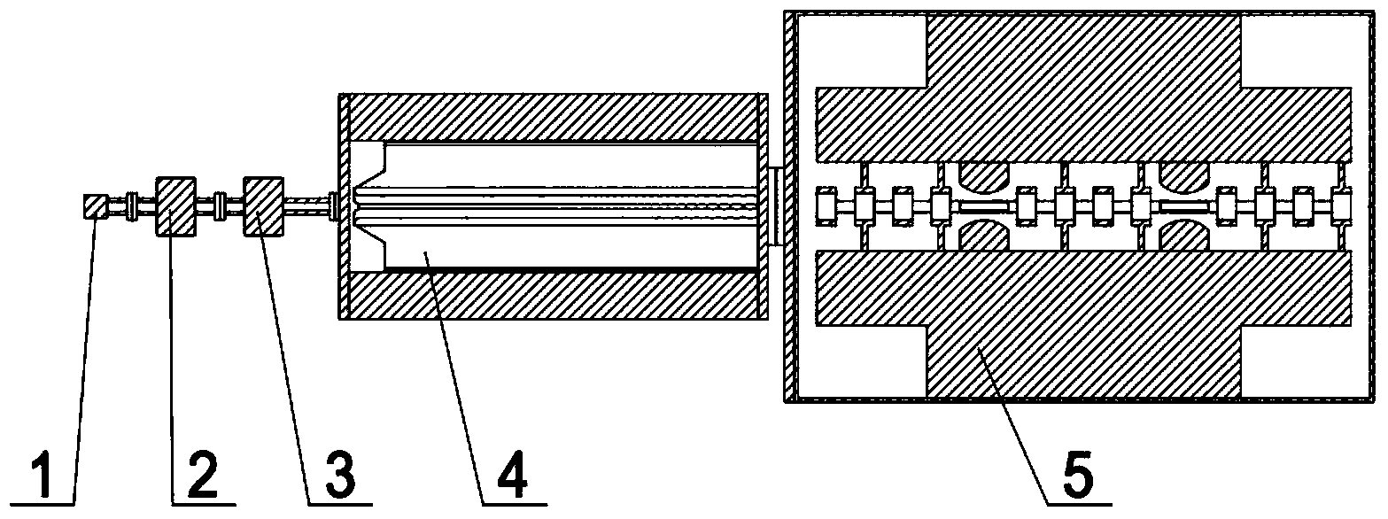
[0027] Example 1: see figure 1 , an ion accelerator implantation device, including an ion beam flow ECR ion source 1 for generating high current intensity and a first solenoid 2 and a second solenoid 3 connected to an RFQ linear accelerator 4 and a hybrid ion accelerator DTL5 through a vacuum pipeline . The RFQ linear accelerator 4 and the hybrid ion accelerator DTL5 are connected by flanges.

[0028] In the ECR ion source 1, a high voltage of 20KV is drawn from the suction pole, and the cyclotron frequency is 2GHz.

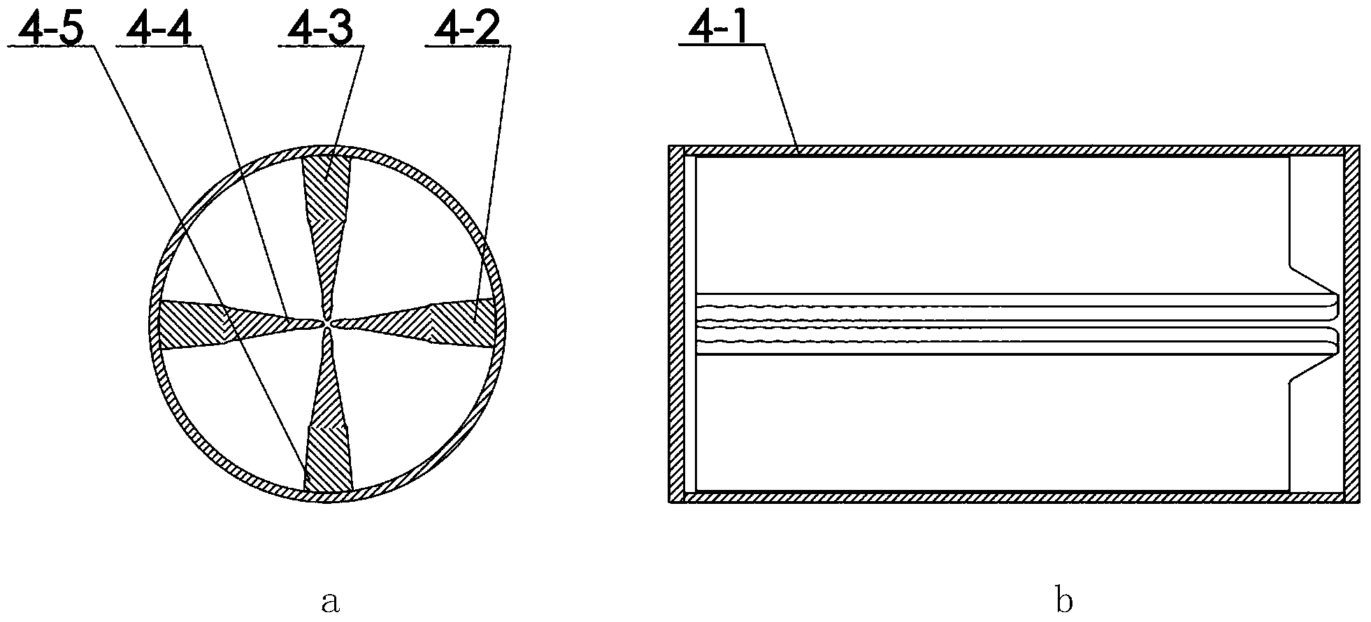
[0029] See figure 2 (a), figure 2 (b), the RFQ linear accelerator 4 includes a vacuum chamber barrel 4-1 and four electrodes 4-2, 4-3, 4-4, 4-5 perpendicular to each other, and the surface of the electrodes presents a wave-shaped modulation surface. The distance between the two opposite electrodes 4-2 and 4-4 is a variable pitch, and the pitch range is 2mm-10mm; the distance between the two opposite electrodes 4-3 and 4-5 is a variable pitch, and the pitch...

Embodiment 2

[0037] Example 2: see figure 1 , an ion accelerator implantation device, including an ion beam flow ECR ion source 1 for generating high current intensity and a first solenoid 2 and a second solenoid 3 connected to an RFQ linear accelerator 4 and a hybrid ion accelerator DTL5 through a vacuum pipeline . The RFQ linear accelerator 4 and the hybrid ion accelerator DTL5 are connected by flanges.

[0038] The ECR ion source 1 has a high voltage of 100KV drawn from the suction pole, and a cyclotron frequency of 30GHz.

[0039] See figure 2 (a), figure 2(b), the RFQ linear accelerator 4 includes a vacuum chamber barrel 4-1 and four electrodes 4-2, 4-3, 4-4, 4-5 perpendicular to each other, and the surface of the electrodes presents a wave-shaped modulation surface. The distance between the two opposite electrodes 4-2 and 4-4 is a variable pitch, and the pitch range is 2mm-10mm; the distance between the two opposite electrodes 4-3 and 4-5 is a variable pitch, and the pitch ran...

Embodiment 3

[0047] Embodiment 3: see figure 1 , an ion accelerator implantation device, including an ion beam flow ECR ion source 1 for generating high current intensity and a first solenoid 2 and a second solenoid 3 connected to an RFQ linear accelerator 4 and a hybrid ion accelerator DTL5 through a vacuum pipeline . The RFQ linear accelerator 4 and the hybrid ion accelerator DTL5 are connected by flanges.

[0048] The ECR ion source 1 has a high voltage of 60KV drawn from the suction pole, and a cyclotron frequency of 20GHz.

[0049] See figure 2 (a), figure 2 (b), the RFQ linear accelerator 4 includes a vacuum chamber barrel 4-1 and four electrodes 4-2, 4-3, 4-4, 4-5 perpendicular to each other, and the surface of the electrodes presents a wave-shaped modulation surface. The distance between the two opposite electrodes 4-2 and 4-4 is a variable pitch, and the pitch range is 2mm-10mm; the distance between the two opposite electrodes 4-3 and 4-5 is a variable pitch, and the pitch ...


PUM


Abstract

The invention relates to an ion accelerator injection device, and belongs to the technical field of nuclear energy. The ion accelerator injection device is characterized in that the ion accelerator injection device comprises an ion beam current ECR ion source, a first solenoid, a second solenoid, an RFQ linear accelerator and a mixed type ion accelerating device, wherein the ion beam current ECR ion source is used for generating high intensity, and the first solenoid and the second solenoid are connected with the RFQ linear accelerator and the mixed type ion accelerating device through vacuum pipelines. The RFQ linear accelerator and the mixed type ion accelerating device are connected through a flange. The ion accelerator injection device has the advantages that in the accelerating process of high intensity ion beam currents, the quality of the beam currents is made to be better due to the fact that the structure is more compact; the accelerating function and the transverse and longitudinal focusing function are combined in the same high-frequency structure by using the accelerating function of a mixed type DTL, cavity shunt impedance is high, and high-frequency power dissipation is lowered greatly; acceleration is carried out by using a zero phase, acceleration efficiency is higher, the length of a cavity can be reduced effectively, and effective accelerating gradients can be improved; an additional transmission matching section is not needed between an RFQ and the mixed type DTL, manufacturing cost can be lowered, and the length of the device can be shortened. The ion accelerator injection device is mainly applied to acceleration of high intensity low energy ion beam currents, and can be applied to injection devices of high-current accelerators, industrial accelerators and other application type accelerating devices.

Description

technical field [0001] The invention relates to an ion implanter device, which belongs to the technical field of nuclear energy. Background technique [0002] Protons and heavy ions are more and more widely used in scientific research, industry, medical treatment, aerospace and other fields. High-energy ion beams can carry out scientific research in nuclear physics and nuclear celestial bodies; the application of 230MeV / u-400MeV / u ion beams in cancer treatment has been considered one of the most effective methods in the world today; 10MeV / u u's ion beam currents are widely used in ion implantation, irradiation pharmaceuticals, isotope generation and other applications. [0003] In the implementation of the above applications, the ion implanter is the most basic device. The ion implanter can provide the acceleration of different ions from proton to uranium beam according to the need, and can provide the beam current within 10MeV / u according to the demand of the downstream a...

Claims


Application Information

Patent Timeline
Patent Type & Authority Applications(China)
IPC IPC(8): H05H7/08
Inventor 王志军何源刘鲁北
Owner INST OF MODERN PHYSICS CHINESE ACADEMY OF SCI
Why Eureka
Try Eureka