
Hom damped high-frequency resonator

a high-frequency resonator and hom technology, applied in accelerators, electric discharge tubes, electrical apparatus, etc., can solve the problems of limited connection utility, large shunt impedance reduction, and high operating cost, and achieve energy-efficient acceleration, simple structure of cooling water ducts, and high hom attenuation.

Inactive Publication Date: 2004-08-26
HELMHOLTZ ZENT BERLIN FUER MATERIALIEN & ENERGIE GMBH
View PDF1 Cites 0 Cited by
  • Summary
  • Abstract
  • Description
  • Claims
  • Application Information

AI Technical Summary

Benefits of technology

[0043] It is, therefore, an object of the invention to provide for a compact HOM-attenuated HF-resonator of improved attenuation properties which can be manufactured cost-efficiently and which, at the same time, is of high shunt impedance as regards the fundamental mode
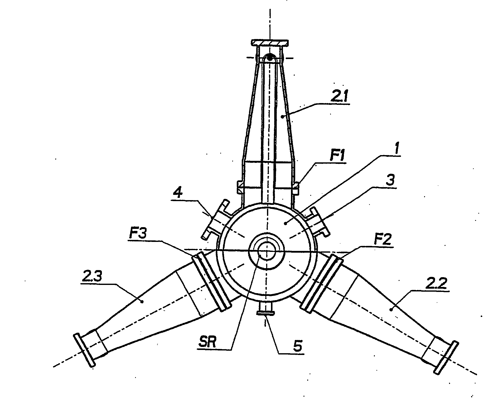
[0047] Since the structure of the waveguides is such that their angularity relative to the axis of the cylindrical resonator cavity may be adjusted, for instance by being connected to the resonator cavity by rotationally symmetric UHV (ultra high vacuum) flanges, the orientation of the waveguide ridge relative to the beam axis is selectable. This makes it possible selectively to optimize the coupling to individual HOM's which are particularly disturbing in a specific storage ring.
[0049] The setting of the angularity of the waveguide ridge relative to the axis of the cylindrical resonator chamber in particular by means of rotationally symmetric flanges makes possible an optimum coupling of particularly disturbing HOM's.
[0050] In one embodiment, the ridges of the waveguides are aligned parallel relative to the axis of the cylindrical resonator cavity, i.e. the angle of the ridge waveguides with respect to the axis of the cylindrical resonator chamber is zero degrees. This embodiment constitutes the optimum solution in cases in which all HOM's are excited by the electron beam with the same power. Where this is not the case, the adjustability of the orientation of the waveguide ridges allows for a minimization of the HOM's specific to the storage ring.
[0054] For optimizing the shunt impedance of the fundamental mode, the resonator cavity, in a further embodiment, is provided with a beam hole of nose-like expansions. This utilized nose-cone geometry in the area of the beam hole results in a concentration of the accelerated field on the axis of the resonator which leads to a large shunt impedance and, at the same time, a high HOM attenuation. The realization of a high shunt impedance ensures a more energy-efficient acceleration of the electron beam during operation of the accelerator, relative to prior art arrangements.
[0055] By its compact structure, the solution in accordance with the invention makes possible the utilization of HOM attenuated resonators in most synchrotron radiation sources. With round waveguides, the maximum local thermal energy densities on the interior surface of the resonator in the transition area between waveguide and resonator wall (at an external energization of the base mode) are about 50% lower than with rectangular waveguides. This makes possible a significantly simpler structuring of the cooling water ducts. Seen from the point of view of construction, the connection of a round waveguide with a cylindrical resonator is simpler and more cost efficient than is the connection between a rectangular waveguide with a spherical or ball-shaped arrangement. Compared to solutions mentioned in the prior art, the manufacturing costs amount to about 40% only. The nose-cone geometry used for structuring the beam hole results--as has been mentioned already--in a high shunt impedance of the fundamental mode at a simultaneous more efficient HOM attenuation.

Problems solved by technology

This advantage is, however, achieved at the expense of a significantly reduced shunt energy of the basic made which results in higher operating costs.
Both mentioned resonators have been developed for use in electron-positron-storage rings for high energy physics with extended straight sections and are thus of limited utility in connection with synchrotron radiation sources.
As has already been mentioned, it was possible to reduce the dimensions of a HOM-attenuated high frequency resonator; however, the reduction of the shunt impedance of the fundamental mode is relatively large and the attenuation efficiency for higher order modes is insufficient.

Method used


Image

  • Hom damped high-frequency resonator
  • Hom damped high-frequency resonator
  • Hom damped high-frequency resonator

Examples


Embodiment Construction

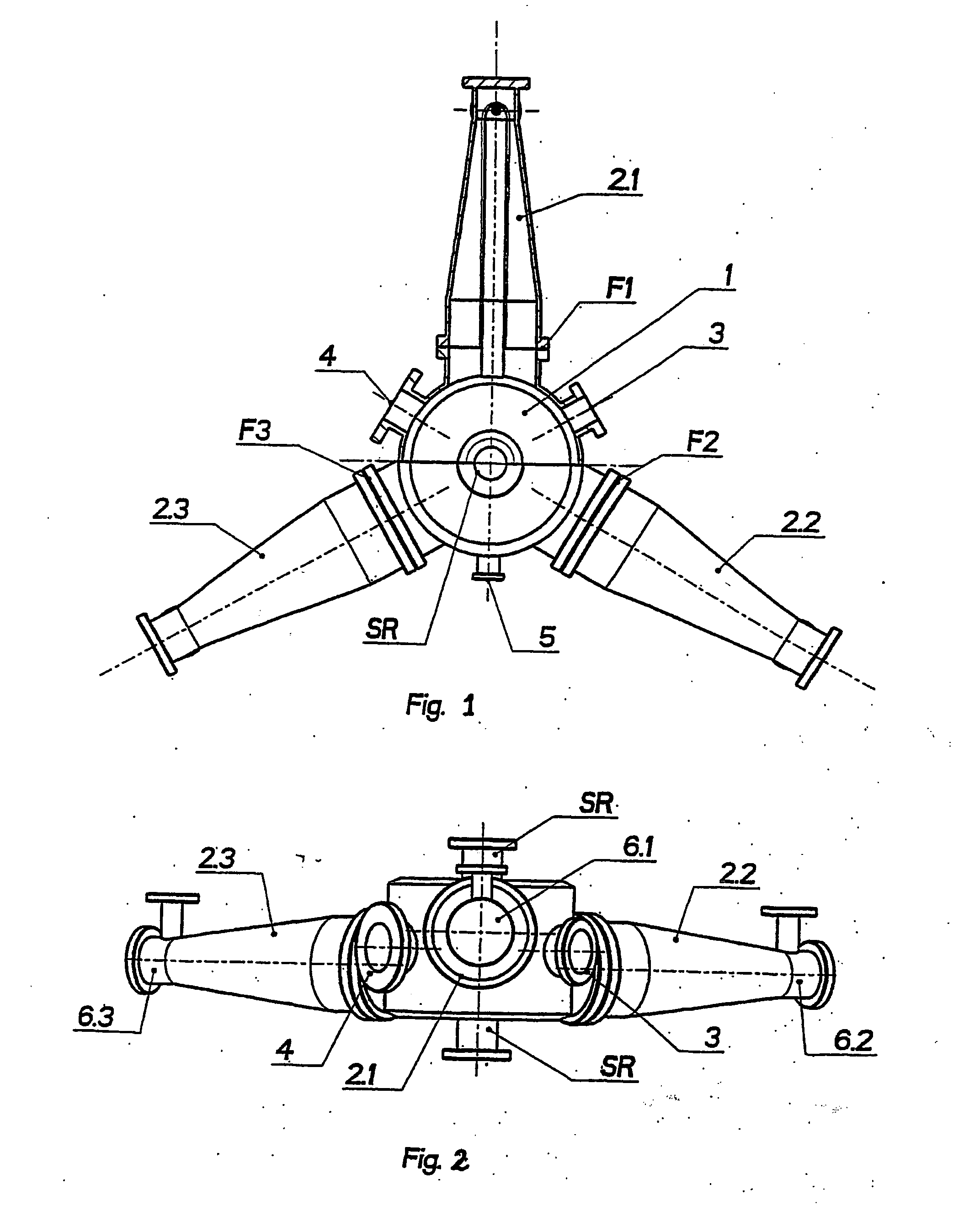
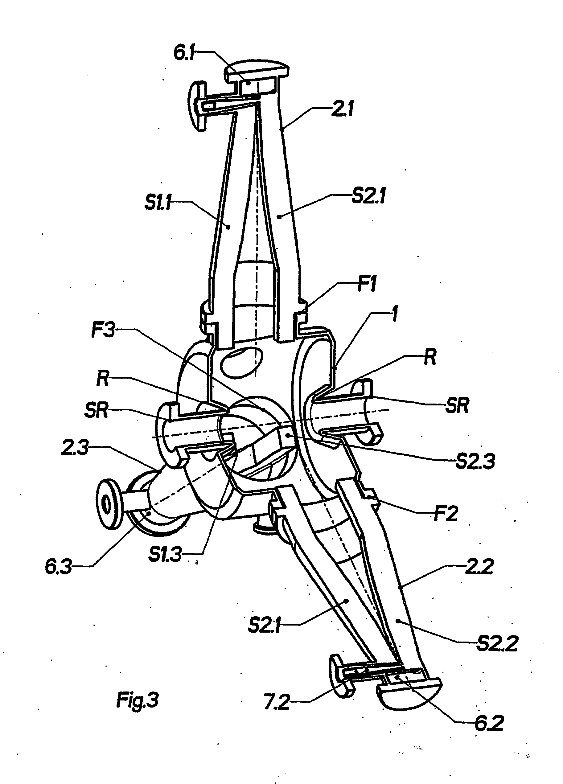
[0061] A HOM attenuated HF resonator is schematically depicted in FIG. 1. In a normally conducting 500 MHz acceleration resonator for synchrotron sources, three circular ridge waveguides 2.1; 2.2; 2.3 are mounted by flanges F1; F2; F3 on a cylindrical resonator cavity 1. The flanges F1; F2; F3 allow setting the orientation of the rides of the waveguides 2.1; 2.2, 2.3. The figure also shows the opening for an input coupling element 4, the opening for the tuner 3, and the opening for the connector to a measuring loop 5.

[0062] In the side view according to FIG. 1 schematically shown in FIG. 2, the offset relative to each other of the three waveguides 2.1; 2.2; 2.3 disposed on the outer surface of the resonator cavity 1 in the direction of its longitudinal axis may be well recognized. This figure also depicts the impedance transformers 6.1; 6.2; 6.3. The shown offset in accordance with the invention of the waveguides 2.1; 2.2; 2.3 with respect to each other results in an efficient outpu...


PUM


Abstract

A HOM attenuated high frequency resonator provided with a cylindrical resonator cavity on the outer surface of which are arranged three circular tapered waveguides with two symmetrically arranged ridges each, the cut-off frequency of the waveguide base mode being kept constant over the length of the waveguides by varying the height of the ridges, and the ridge waveguides being provided at their end of the smaller diameter with an impedance transformer each for the broadband adjustment of the coaxial line is to be cost-efficiently manufacturable as a compact structure and is to be of improved attenuation properties while at the same time having, relative to prior art arrangements, a high shunt impedance for the fundamental modes.

Description

[0001] The invention relates to a HOM attenuated high frequency resonator provided with a cylindrical resonator cavity on the outer surface of which there are arranged three circular tapered waveguides with two symmetrically disposed connector elements, the cut-off frequency of the waveguide basic mode being kept constant over the length of the waveguides by varying the height of the connector element, the ridge waveguides at their smaller diameter end being provided with an impedance transformer for broadband HF adjustment of the coaxial line.[0002] In electron storage rings for generating synchrotron radiation the brilliancy of the photon beams decisively depends upon the quality of the stored electron beam. Beam instabilities in particular negatively affect the generated brilliancy. The beam instabilities are cause by multibunch oscillations which cause an enlargement of the power width (longitudinal oscillations) and of the transverse emittance (transverse oscillations).[0003] T...

Claims


Application Information

Patent Timeline
Patent Type & Authority Applications(United States)
IPC IPC(8): H05H7/18
CPCH05H7/18
Inventor WEIHRETER, ERNSTMARHAUSER, FRANK
Owner HELMHOLTZ ZENT BERLIN FUER MATERIALIEN & ENERGIE GMBH
Learn More