Internally-disposed-profile-steel steel pipe concrete frame low-yield-point steel plate shear wall structure

A steel plate shear wall and concrete-filled steel tube technology, which is applied in the direction of walls, building components, building structures, etc., can solve the problems of insufficient utilization of steel and reduce the interaction between steel and concrete, and achieve superior seismic performance and hysteresis. The curve is plump and the effect of reducing welding deformation

Inactive Publication Date: 2014-07-09
BEIJING JIAOTONG UNIV
View PDF6 Cites 16 Cited by
  • Summary
  • Abstract
  • Description
  • Claims
  • Application Information

AI Technical Summary

Problems solved by technology

In this application, the anchor steel plate only plays the role of a shear connector and does not participate in the force of the steel tube concrete. The steel is not fully utilized, and it is easy to cause large welding deformation
[0005] On the other hand, in the traditional steel-concrete structure, it is common practice to keep the natural bond between the steel and concrete without any treatment, which will cause unpredictable relative slippage between the steel and concrete, coupled with the steel plate shear wall. The strong tension field will greatly reduce the joint action of steel and concrete

Method used


Image

  • Internally-disposed-profile-steel steel pipe concrete frame low-yield-point steel plate shear wall structure
  • Internally-disposed-profile-steel steel pipe concrete frame low-yield-point steel plate shear wall structure
  • Internally-disposed-profile-steel steel pipe concrete frame low-yield-point steel plate shear wall structure

Examples


Embodiment Construction

[0043] In order to illustrate the present invention more clearly, the present invention will be further described below in conjunction with preferred embodiments and accompanying drawings. Similar parts in the figures are denoted by the same reference numerals. Those skilled in the art should understand that the content specifically described below is illustrative rather than restrictive, and should not limit the protection scope of the present invention.

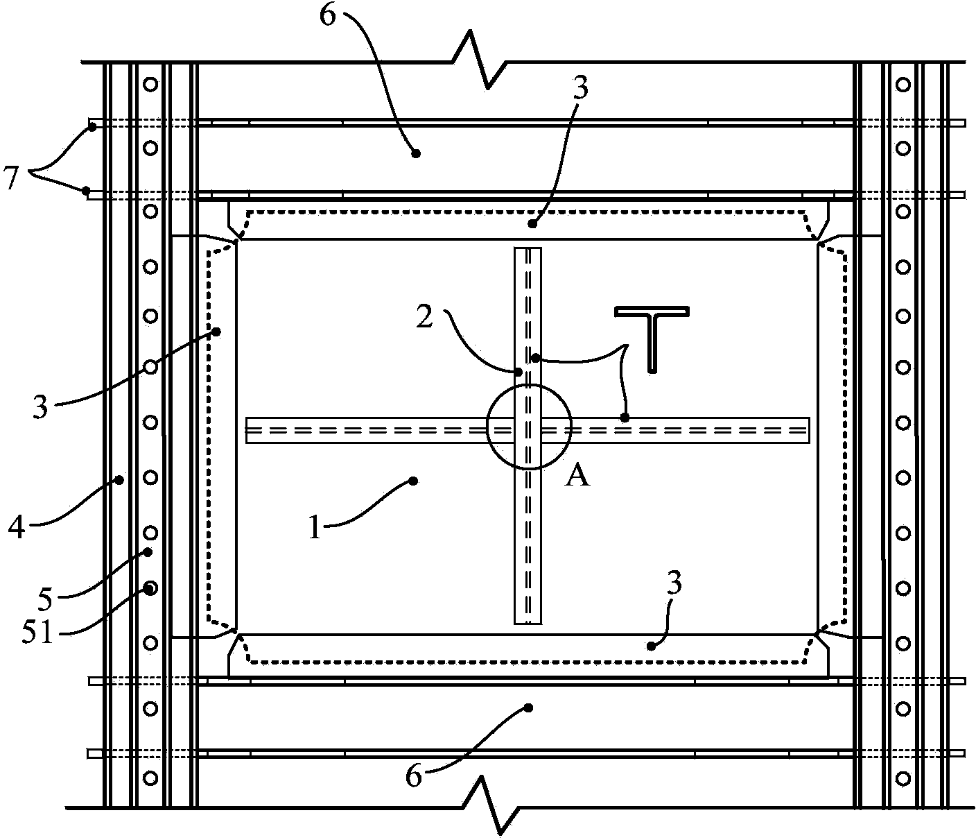
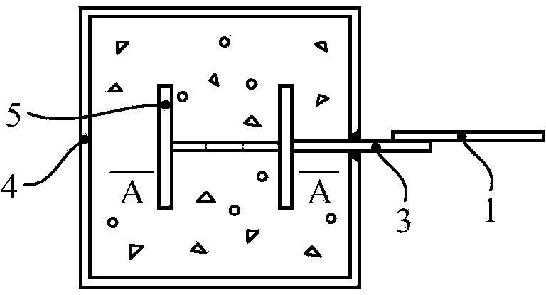
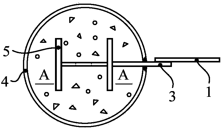
[0044] like Figure 1~4 As shown, a low-yield-point steel plate shear wall structure with a built-in steel-filled steel tube concrete frame of the present invention includes an embedded steel plate 1, a T-shaped stiffener 2, a fishplate 3, a steel tube concrete side column 4, shaped steel 5 and a "dog bone" Type” steel beams 6. The concrete-filled steel pipe side column 4 is a rectangular steel pipe structure or a circular steel pipe structure. The section steel 5 is arranged inside the steel pipe concrete side column 4. ...


PUM

PropertyMeasurementUnit
yield strengthaaaaaaaaaa
compressive strengthaaaaaaaaaa

Abstract

The invention discloses an internally-disposed-profile-steel steel pipe concrete frame low-yield-point steel plate shear wall structure which comprises steel pipe concrete side columns, steel cross beams and an internally-embedded steel plate. Profile steel is generally arranged inside the steel pipe concrete side columns, each vertical lateral side of the internally-embedded steel plate is connected with a fishtail plate, the fishtail plates penetrate the side walls of the steel pipe concrete side columns to be connected with the profile steel in a welded manner, and positions where the fishtail plate are intersected with the side walls of the steel pipe concrete side columns are in welded connection. The profile steel is throughly arranged along the height direction of each steel pipe concrete side column, the profile steel and the steel pipe concrete side columns are jointly stressed, the profile steel plays a role as a shear connector and also plays a role of improving vertical bearing capacity of the steel pipe concrete side columns, so that using efficiency of the profile steel is improved. Sectional size of the side columns can be substantially reduced while requirements of the bearing capacity of the steel pipe concrete side columns are met, dead weight of the structure is reduced, seismic ductility of the structure is improved, building using space is effectively increased, and the structure is especially suitable for high-rise and ultrahigh-rise building structures.

Description

technical field [0001] The invention relates to the field of steel plate shear wall structures, and more particularly relates to a low yield point steel plate shear wall structure with a built-in steel tube concrete frame. Background technique [0002] The steel plate shear wall structure is a new type of lateral force-resisting structural system developed in the 1970s. The steel plate shear wall is composed of embedded steel plates, vertical edge members (columns) and horizontal edge members (beams). , the embedded steel plate is equivalent to the beam web, and the horizontal edge member can be approximately equivalent to the transverse stiffener. Embedded steel plates can be constructed without stiffeners or with stiffeners. Unstiffened steel plate shear walls can make full use of the post-buckling strength of steel plates under strong earthquakes, and have good ductility and energy dissipation capacity. The stiffened steel plate shear wall can limit the out-of-plane bu...

Claims


Application Information

Patent Timeline
Patent Type & Authority Applications(China)
IPC IPC(8): E04B2/56E04B2/58E04B1/98
Inventor 王萌杨维国
Owner BEIJING JIAOTONG UNIV
Why Eureka
Try Eureka