Electric hydrodynamic force propeller

A fluid power and thruster technology, applied in the aerospace field, can solve problems such as low efficiency and small thrust, and achieve the effect of increasing the thrust-to-weight ratio and improving propulsion efficiency

Inactive Publication Date: 2014-07-09
XIAN RUOSHUI ELECTRICAL EQUIP CO LTD
View PDF8 Cites 19 Cited by
  • Summary
  • Abstract
  • Description
  • Claims
  • Application Information

AI Technical Summary

Problems solved by technology

[0005] A large number of studies have found that the two key bottleneck

Method used


Image

  • Electric hydrodynamic force propeller
  • Electric hydrodynamic force propeller
  • Electric hydrodynamic force propeller

Examples


Embodiment Construction

[0028] The structural principle and working principle of the present invention will be further described in detail below in conjunction with the accompanying drawings.

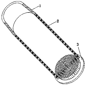
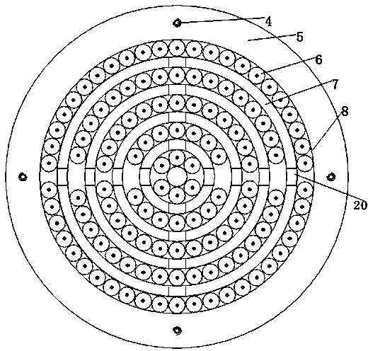
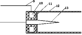
[0029] see figure 1 , figure 2 , image 3 , Figure 4 , Figure 5 ,

[0030] This embodiment is a propeller that can be used for aerospace vehicles, including a converging nozzle 1, a synchrotron 2, an alternating positive and negative plasma generator 3, a screw hole 4, a support plate 5, an alternating positive and negative Plasma emission unit 6, air channel 7, connection plate 8, wire 9, high-frequency ring electrode 10, insulating material 11, alternating positive and negative plasma emission unit tube body 12, high-frequency high-voltage tip electrode 13, screw assembly Hole 14, synchrotron unit 15, accelerator tube wall 16, grounding 17, wire 18, high-frequency pulse power supply 19.

[0031] see figure 1 , 2, the alternating positive and negative plasma generator 3 is composed of a screw hole ...


PUM


Abstract

The invention relates to an electric hydrodynamic force propeller which comprises a contracting nozzle connected with a synchronous multistage accelerator. An alternating positive-negative plasma generator is fixed at the air inlet end of the synchronous multistage accelerator. A support plate is disposed at the outer edge of the alternating positive-negative plasma generator. Connecting plates are located on the inner side of the support plate. Every two adjacent layers of connecting plates and the corresponding hollow connecting plate enclose an air passage. Each annular electrode is connected with a high-frequency pulse power supply, which is grounded, through a wire. An alternating positive-negative plasma emitting unit is disposed in each mounting hole. Each high-frequency tip electrode and the corresponding high-frequency circular electrode form corona discharge, the plasma of the corresponding alternating positive-negative plasma emitting unit is sprayed, the plasma mixed with the air flowing in from the air passage enters the synchronous multistage accelerator, and charge particles and the air accelerated by the synchronous multistage accelerator enter the contracting nozzle and are sprayed out by the same after acceleration. By the electric hydrodynamic force propeller, bottlenecks of high temperature and high pressure are overcome, aero-space flight is achieved, high specific impulse and propelling efficiency are achieved, and propellant mass is reduced.

Description

technical field [0001] The invention belongs to the field of aerospace technology, and in particular relates to an electric fluid power propeller. Background technique [0002] In the current field of propulsion, the propulsion efficiency of traditional solid rocket motors and liquid rocket motors is low, the mass of propellant carried is large, and the payload is relatively small; traditional turbojet, turbofan and other aircraft engines cannot achieve aerospace flight, and there are bottlenecks such as high temperature and high pressure; new concept engines such as ramjet engines and pulse detonation engines cannot achieve aerospace flight; although the newly proposed electrohydrodynamic thrusters and magnetic fluid thrusters have high specific impulses, they are not suitable Atmospheric flight. Therefore, the development of a new propulsion technology with high energy utilization rate to realize aerospace flight has important engineering application prospects and practic...

Claims


Application Information

Patent Timeline
IPC IPC(8): F03H1/00
Inventor 王文东李世武王泽元魏建生
Owner XIAN RUOSHUI ELECTRICAL EQUIP CO LTD
Why Eureka
Try Eureka