Hydraulic oil temperature control system and engineering machinery

A technology for control systems and construction machinery, applied in fluid pressure actuation system components, mechanical equipment, fluid pressure actuation devices, etc., can solve the problems of increased engine fuel consumption, reduced engine efficiency, and high engine water temperature, and reduced leakage. , Increase the cycle period and cooling time, the effect of a wide range of applications

Inactive Publication Date: 2014-07-09
SANY HEAVY MACHINERY
View PDF9 Cites 10 Cited by
  • Summary
  • Abstract
  • Description
  • Claims
  • Application Information

AI Technical Summary

Problems solved by technology

[0003] In order to reduce the temperature of the hydraulic oil and avoid high temperature and low efficiency, many construction machinery manufacturing companies usually adopt the following two solutions: one is to use a larger pulley or a larger radiator to reduce the hydraulic oil temperature by increasing the air intake, but This will reduce the efficiency of the engine, or black smoke will appear at low gears; the second is to use the heat exchange of the air conditioner to take away the heat of the hydraulic oil, thereby reducing the temperature of the hydraulic oil, but this solution will increase the cost, and the fuel consumption of the engine will decrease. Increased, but also cause the phenomenon of engine water temperature is too high

Method used


Image

  • Hydraulic oil temperature control system and engineering machinery

Examples


Embodiment Construction

[0022] It should be noted that, in the case of no conflict, the embodiments of the present invention and the features in the embodiments can be combined with each other. The present invention will be described in detail below with reference to the accompanying drawings and examples.

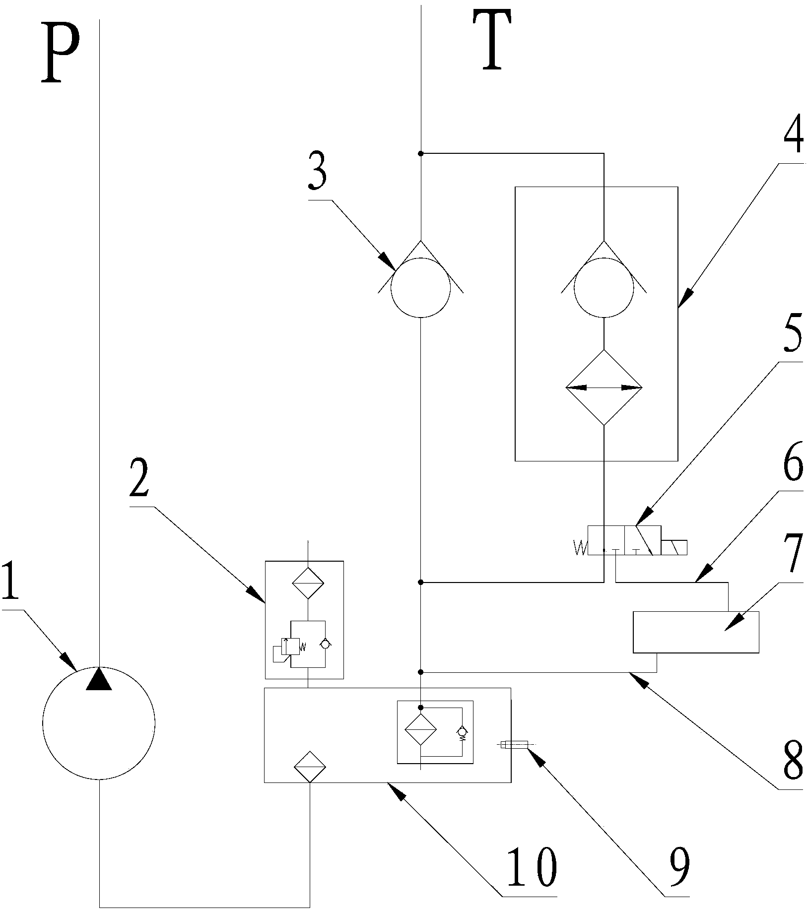
[0023] figure 1 That is the relevant drawings of this embodiment, as shown in the figure, the hydraulic oil temperature control system described in this embodiment includes a pump 1, a main oil tank 10 communicated with the oil inlet of the pump 1, and a main oil tank 10 communicated with the main oil tank 10. The oil return circuit of the oil return circuit and the radiator 4 arranged on the oil return circuit also include an auxiliary oil tank 7 communicating with the main oil tank 10, a switch for connecting the radiator 4 and the main oil tank 10 or connecting the radiator 4 and the auxiliary oil tank 7 The directional valve 5, the temperature sensor 9 used to detect the temperature of the h...


PUM


Abstract

The invention provides a hydraulic oil temperature control system and engineering machinery. The hydraulic oil temperature control system comprises a pump, a main oil tank, an oil return circuit, a radiator, an auxiliary oil tank, a reverse valve, a temperature sensor and a controller. When the hydraulic oil temperature in the main oil tank is higher than a preset value, the controller controls the reverse valve to cut off the oil circuit between the radiator and the main oil tank and communicates with another oil circuit between the radiator and the auxiliary oil tank; when the hydraulic oil temperature in the main oil tank is lower than the preset value, the controller controls the reverse valve to cut off the oil circuit between the radiator and the auxiliary oil tank and communicates with the oil circuit between the radiator and the main oil tank. By the arrangement, the auxiliary oil tank can be selectively connected or disconnected according to the hydraulic oil temperature in the main oil tank, so that the hydraulic oil temperature can be sustained within the best temperature range, leakage of hydraulic oil can be further reduced, and operation efficiency of the hydraulic system can be improved while the service life of the same can be prolonged.

Description

technical field [0001] The invention relates to the field of hydraulic technology, in particular to a hydraulic oil temperature control system and engineering machinery. Background technique [0002] In the hydraulic system of construction machinery, the effective volume of the hydraulic oil tank should be 3-7 times the flow rate of the main pump. 0.6 times, resulting in too short a hydraulic oil cycle and reduced service life. The hydraulic oil temperature of construction machinery is controlled at 30-50°C for the best performance. When the oil temperature is higher than 65°C, the viscosity of the oil will decrease, the oil film will be easily damaged, the leakage will increase, and the efficiency will decrease. If the working temperature of the hydraulic oil is higher than the optimal temperature, when the oil temperature is higher than 65°C, the service life of the hydraulic oil and hydraulic components will be reduced by half for every 10°C increase. [0003] In order ...

Claims


Application Information

Patent Timeline
Patent Type & Authority Applications(China)
IPC IPC(8): F15B21/04
Inventor 俞宏福余先照彭双成叶其团
Owner SANY HEAVY MACHINERY
Why Eureka
Try Eureka