Optical fiber sensor array and antenna pattern measuring device and measuring method

A fiber optic sensor and antenna pattern technology, applied in the antenna radiation pattern and other directions, can solve the problems of slow measurement speed, small light pulse duty cycle, increased measurement error, etc., to achieve convenient maintenance, easy synchronization, and avoid excessive requirements Effect

Active Publication Date: 2014-07-09
NANJING UNIV OF AERONAUTICS & ASTRONAUTICS
View PDF5 Cites 18 Cited by
  • Summary
  • Abstract
  • Description
  • Claims
  • Application Information

AI Technical Summary

Problems solved by technology

[0004] (1) The receiving antenna is implemented based on metal materials, which will inevitably cause disturbances in the electromagnetic field radiated by the antenna under test, resulting in large errors in the measurement results;
[0005] (2) Limited by the working bandwidth of the receiving antenna, this method cannot realize the measurement of the broadband pattern;
[0006] (3) When measuring the antenna pattern, it is necessary to use sophisticated equipment to move the receiving antenna or rotate the antenna to be tested, which is expensive, slow in measurement speed, and cannot measure the real-time response of the antenna;
The main problems of this method are: ① To make the optical pulses have no pulse-to-pulse crosstalk during multiplexing, the edges of the optical pulses are required to be very steep and the shape is close to a rectangle; however, the spectral components of the rectangular pulses are very rich, which disperses the energy on the frequency to be detected , thereby reducing the detection efficiency or increasing the measurement error; ② To multiplex more sensor information, the duty cycle of the optical pulse is required to be very small in order to insert more pulses, and the optical carrier pulse with a low duty cycle is difficult In addition, the bandwidth of the lock-in amplifier in the weak signal detection device is very small (generally on the order of hundreds of kHz), and it does not even respond to signals with too low duty cycle, thus reducing the scalability of the scheme

Method used


Image

  • Optical fiber sensor array and antenna pattern measuring device and measuring method
  • Optical fiber sensor array and antenna pattern measuring device and measuring method
  • Optical fiber sensor array and antenna pattern measuring device and measuring method

Examples


Embodiment Construction

[0018] The technical scheme of the present invention is described in detail below in conjunction with accompanying drawing:
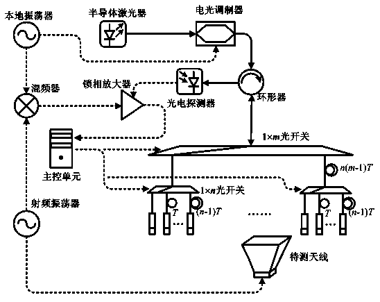
[0019] The idea of ​​the invention is to realize the time-division multiplexing of sensor array data by using the optical switch array combined with the corresponding delay scheme, and realize the instantaneous measurement of the antenna pattern based on the scheme.

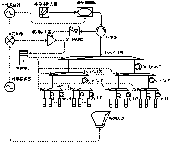
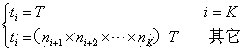
[0020] The optical fiber sensor array of the present invention includes a K-level optical switch array, K is an integer greater than or equal to 1; the first level of the K-level optical switch array is a 1×n 1 The optical switch, the second level is n 1 1×n 2 of optical switches, and so on, the Kth level is n K-1 1×n K The optical switches of all levels are sequentially connected by optical fibers with delay lines to form a 1×(n 1 ×n 2 ×…×n K ) of class K optical switch arrays, where n 1 , n 2 ,...,n K are integers greater than 1; the K-th level of the K-level optical switch arra...


PUM


Abstract

The invention discloses an optical fiber sensor array, and belongs to the technical field of electromagnetic measurement and the microwave photonics. The optical fiber sensor array comprises a Kth optical switch array and a set of optical fiber sensors connected with ports of the Kth optical switch array respectively. The switch time sequence of the optical switch array is controlled, a corresponding delay scheme is combined, time division multiplexing is achieved, and the measurement data of the optical fiber sensors at the same time can be obtained in sequence. The invention further discloses an antenna pattern measuring device and measuring method. The optical fiber sensor array is used for measuring the space electric field intensity of all optical fiber probes at the same time in sequence, and therefore an antenna instant pattern can be measured. Electromagnetic interference caused by a metal probe in the traditional antenna pattern measuring process is eliminated, and spatial resolution, measurement precision and measurement speed are improved. In addition, antenna instant pattern measurement which cannot be achieved by a traditional measurement method can be achieved, and a pulse radar pattern can be measured.

Description

technical field [0001] The invention relates to an optical fiber sensor array, in particular to an optical fiber sensor array capable of realizing time division multiplexing technology, an antenna pattern measuring device and a measuring method using the same. Background technique [0002] The antenna can realize the transmission and reception of microwave signals, and is an indispensable device for many applications such as wireless communication, detection and remote sensing. Direction pattern is a key index to evaluate antenna performance, and has received extensive attention in antenna design and application. In recent years, various applications have higher and higher performance requirements for antennas, forcing the measurement of pattern to develop towards high resolution, high precision and high real-time. [0003] The traditional antenna pattern measurement device uses a standard antenna as the receiving device, and the main challenges it faces are as follows: ...

Claims


Application Information

Patent Timeline
Patent Type & Authority Applications(China)
IPC IPC(8): G01R29/10
Inventor 潘时龙徐威远朱丹张方正薛敏
Owner NANJING UNIV OF AERONAUTICS & ASTRONAUTICS
Why Eureka
Try Eureka