Light-emitting device and projection system

A light-emitting device and wavelength conversion device technology, applied in projection devices, lighting devices, components of lighting devices, etc., can solve the problems of insufficient compactness, complex structure of light-emitting devices, color cast, etc., and achieve the effect of improving the compactness of the structure

Active Publication Date: 2014-07-09
APPOTRONICS CORP LTD
View PDF9 Cites 64 Cited by
  • Summary
  • Abstract
  • Description
  • Claims
  • Application Information

AI Technical Summary

Problems solved by technology

[0004] but, figure 1 The problem with the light-emitting device shown is that the yellow light component and the blue light component in the mixed white light emitted by the lig

Method used


Image

  • Light-emitting device and projection system
  • Light-emitting device and projection system
  • Light-emitting device and projection system

Examples


Embodiment 1

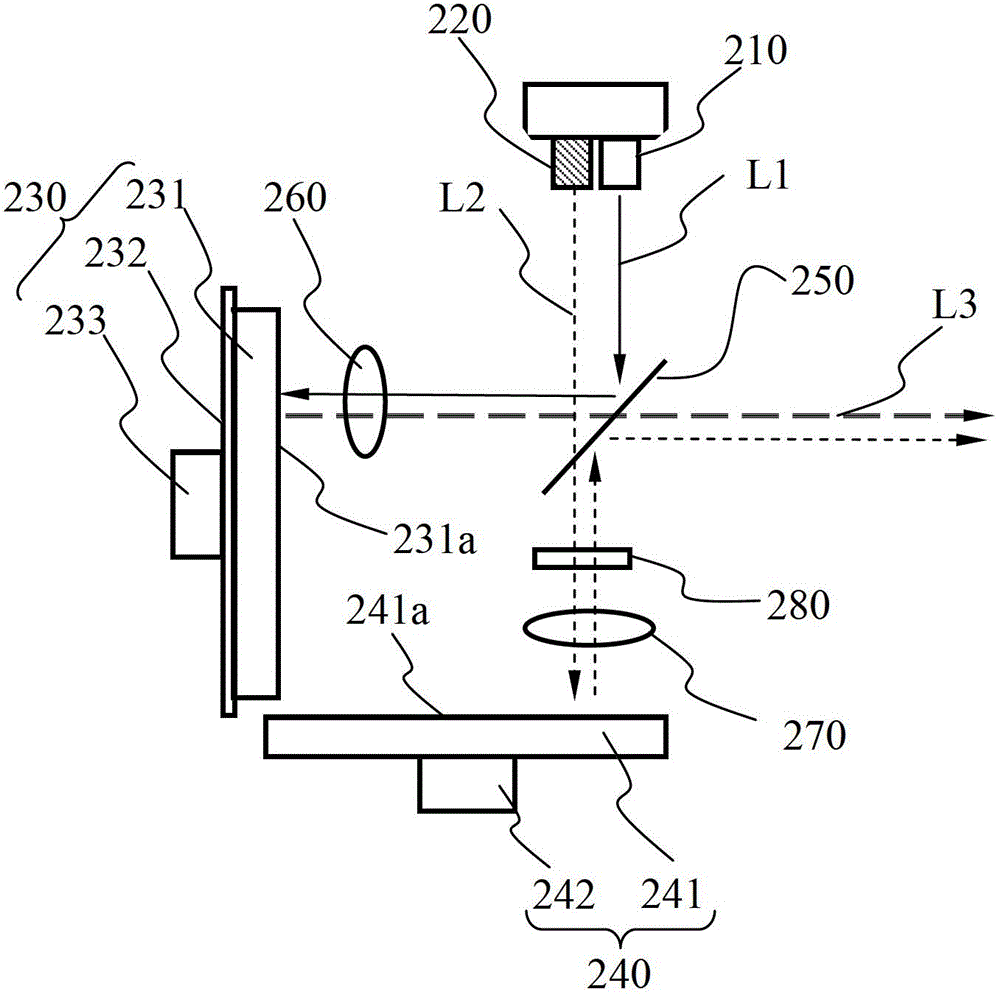
[0037] figure 2 It is a structural schematic diagram of an embodiment of the light-emitting device of the present invention, such as figure 2 As shown, the light emitting device includes a first laser light source 210 , a second laser light source 220 , a wavelength conversion device 230 , a scattering device 240 , an optical path adjustment device 250 , a first lens 260 , and a second lens 270 .

[0038] The first laser light source 210 can emit a first laser light L1, and the second laser light source 220 can emit a second laser light L2. Specifically, the first laser L1 is a 445nm blue laser, which can be used to excite the wavelength conversion material to obtain the received light; the second laser L2 is a 462nm blue laser, which can be used as a blue component for projection display. For the convenience of assembly, the first laser light source 210 and the second laser light source 220 are located in the same light source module and on the same plane of the light sour...

Embodiment 2

[0061] In addition to the difference in the polarization state of the second laser light before scattering and the second laser light after scattering, the optical path adjustment device can also use the difference in etendue of the two. Figure 5 It is a structural schematic diagram of another embodiment of the light-emitting device of the present invention, such as Figure 5 As shown, the light emitting device includes a first laser light source 310 , a second laser light source 320 , a wavelength conversion device 330 , a scattering device 340 , an optical path adjustment device 350 , a first lens 360 , and a second lens 370 .

[0062] The light emitting device in this embodiment and figure 2 The lighting devices shown differ in that:

[0063] (1) In this embodiment, the first laser light source 310 surrounds the second laser light source 320, and the optical path adjustment device 350 includes a filter 352 and a reflective element 351 arranged in the middle of the filter...

Embodiment 3

[0074] This embodiment is another structure in which the etendue of the second laser light L2 before scattering and the second laser light L2 after scattering are different to distinguish the optical path, such as Figure 7 As shown, the light-emitting device includes a first laser light source 410, a second laser light source 420, a wavelength conversion device 430, a scattering device 440, an optical path adjustment device 450, a first lens 460, a second lens 470, a fly-eye lens pair 480, and a diffusion lens 490. .

[0075] The light emitting device in this embodiment and Figure 5 The difference between the light emitting devices shown is that in this embodiment, the optical path adjustment device is a filter 450 with a through hole 451 in the middle, and the area outside the through hole 451 is a filter area 452. At this time, the light source module and the scattering The device 440 is located on both sides of the optical path adjustment device, and the second laser lig...


PUM


Abstract

The embodiment of the invention discloses a light-emitting device and a projection system. The light-emitting device comprises a first laser light source used for emitting first laser, a second laser light source used for emitting second laser, a light-path regulation device, a wavelength conversion device and a scattering device, wherein the light-path regulation device is used for receiving the first laser and the second laser coming in the same direction and enabling the first laser and the second laser to be emitted to the wavelength conversion device and the scattering device respectively along different light paths; the wavelength conversion device comprises a first surface, the first surface is used for receiving the first laser emitted by the light-path regulation device, the first laser is converted into stimulated light through the wavelength conversion device, and the stimulated light is emitted from the first surface to the light-path regulation device; the scattering device comprises a second surface, the second surface is used for receiving the second laser emitted by the light-path regulation device, and the scattering device scatters the second laser and emits the scattered second laser to the light-path regulation device from the second surface; the stimulated light emitted by the wavelength conversion device is combined with the second laser emitted by the scattering device through the light-path regulation device into one light path to be emitted. The device has the advantage of being compact in structure.

Description

technical field [0001] The invention relates to the technical field of illumination and display, in particular to a light emitting device and a projection system. Background technique [0002] Laser phosphor technology is a new type of high-brightness light source solution, which can be widely used in projection display and other fields. Laser phosphor technology uses laser to excite phosphor to generate light as a light source. Since the optical power density of the laser is very high, the optical power density of the stimulated light generated by the excited phosphor is also high, so that the light source can generate high-brightness stimulated light or the mixed light of the stimulated light and the excited light. [0003] figure 1 It is a structural schematic diagram of a light-emitting device in the prior art, such as figure 1 As shown, the wavelength conversion device includes a first laser light source 110, a second laser light source 120, a reflective color wheel ...

Claims


Application Information

Patent Timeline
IPC IPC(8): G03B21/20G03B21/00G02B27/10F21V13/00
CPCG03B21/204H04N9/3161
Inventor 胡飞
Owner APPOTRONICS CORP LTD
Why Eureka
Try Eureka