Laser printing machine for ceramic

A technology of laser printers and ceramics, which is applied in optics, electrical recording technology using charge graphics, equipment using electrical recording technology using charge graphics, etc. The head is easy to block and other problems, so as to overcome the frequent cleaning of the inkjet head, good fidelity, and simple after-sales maintenance.

Active Publication Date: 2014-07-09
陆永添
View PDF4 Cites 8 Cited by
  • Summary
  • Abstract
  • Description
  • Claims
  • Application Information

AI Technical Summary

Problems solved by technology

Among them, planar screen printing is the earliest technology, and the structure of planar screen equipment is the simplest. The printing quality of its pattern and texture is poor, and it needs to be printed by multiple machines, which has been gradually eliminated.
Silicone roller printing is more advanced than flat screen printing, and the equipment is relatively simple. The quality of pattern and texture printing is slightly better than that of flat screen printing machines, and the efficiency is higher. Replace Silicone Roller
The current most popular inkjet printing technology uses color ink printers, which have a large composition and complex structure. The effect of the color pattern texture is still not ideal, there are defects such as dripping ink, inkjet head cable, etc., and the inkjet head is easy to clog, the color of the ink pigment is limited because the pigment particles are too small, and the nozzle is easy to clog when the pigment particles are too large. higher price

Method used


Image

  • Laser printing machine for ceramic
  • Laser printing machine for ceramic
  • Laser printing machine for ceramic

Examples


Embodiment 1

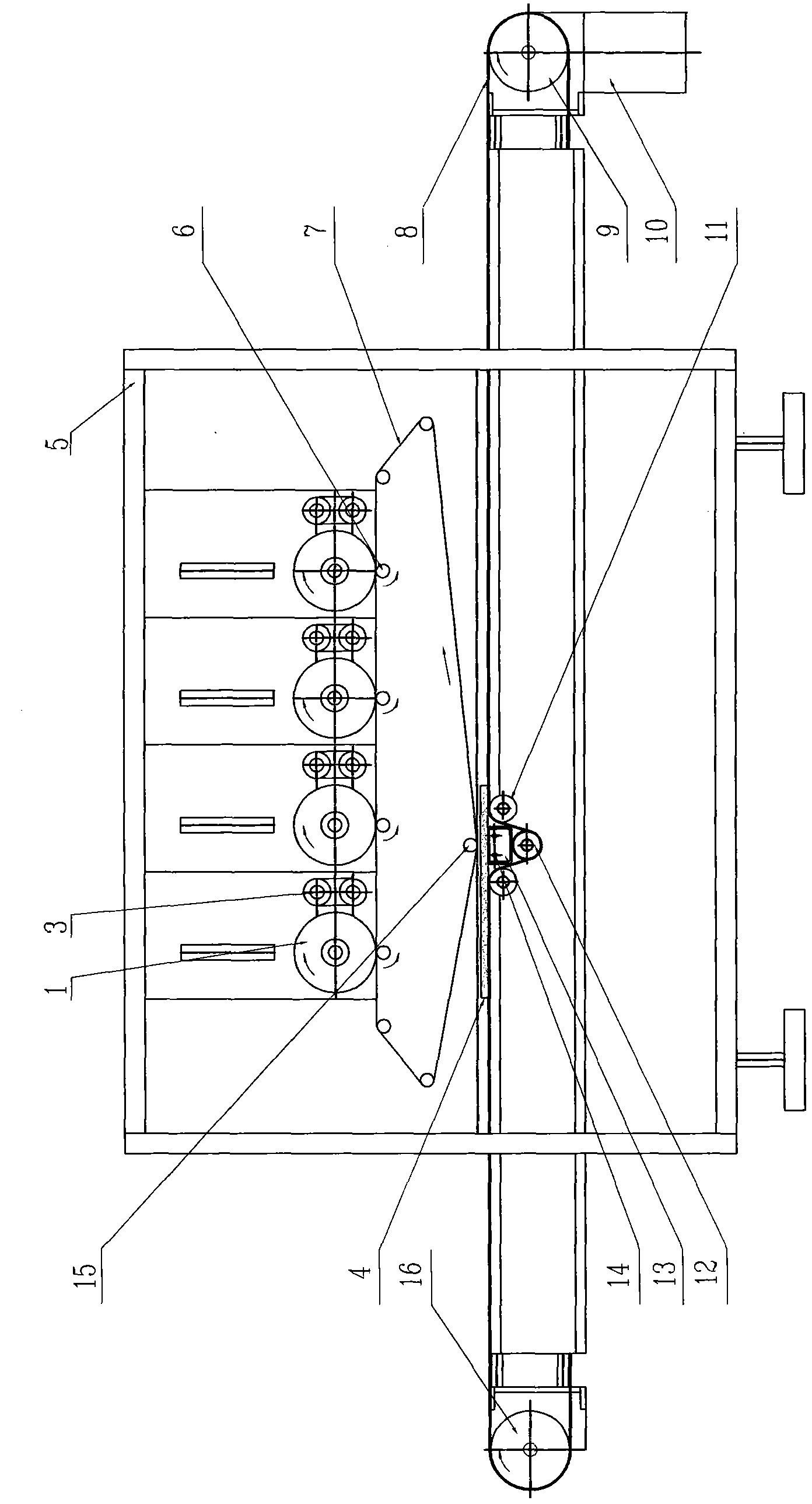
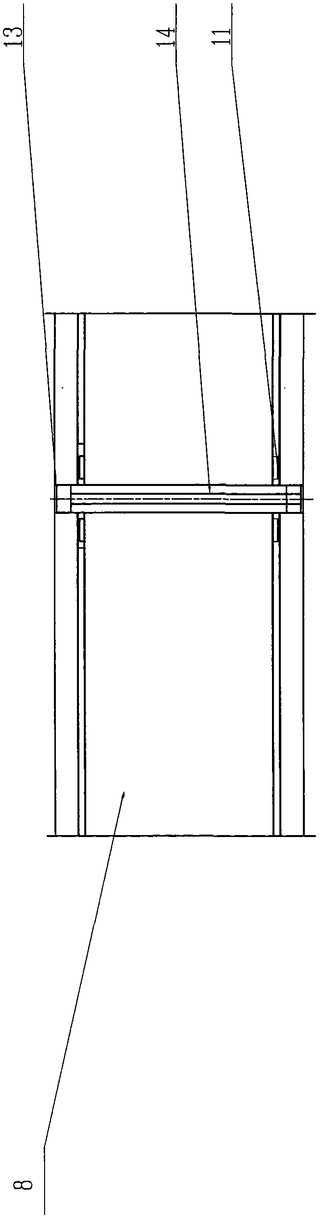
[0017] Embodiment one, see figure 1 and image 3 , between the first pad printing system and the ceramic adobe conveying system, there is a transfer belt 7 which rotates in circulation, and the lower part of the transfer belt 7 forms the closest point with the conveyor belt 8 of the ceramic adobe conveying system, and the closest point is formed by at least The second transfer roller 15 with negative static electricity is tensioned and formed. The closest point is not in contact with the upper surface of the ceramic tile adobe 4 conveyed, leaving a gap of 0.5-3 mm. A positive electrostatic field with a voltage of 2000-20000 volts is provided directly below the passage of the second transfer roller 15 corresponding to the ceramic tile adobe 4 at the closest point, and the positive electrostatic field is arranged longitudinally along the transfer belt 7. The wire seat 13 is formed, and the electrode wire 14 is passed through a high voltage to generate a positive electrostatic ...

Embodiment 2

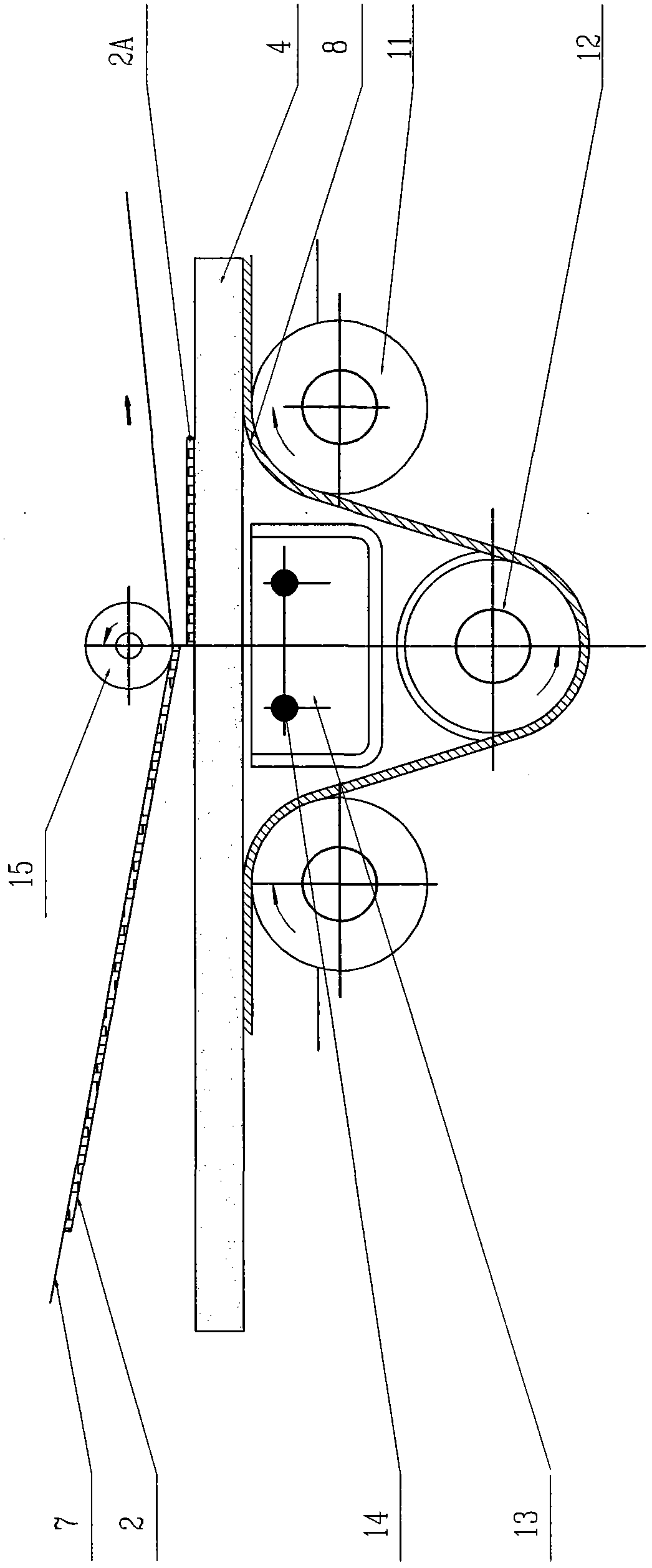
[0019] Embodiment two, see figure 1 and figure 2 , on the basis of the first embodiment above, in order to reduce the impact of the conveyor belt 8 on the electrostatic field, the conveyor belt 8 is improved, in particular: the conveyor belt 8 directly below the closest point corresponding to the transfer belt 7 , there are respectively provided with a pinch roller 12 and a guide roller 11 for changing the direction of the conveyor belt 8, and a pinch roller 2 and two guide rollers 11 are in a character-shaped layout, so that the conveyor belt 8 forms a partially concave space. The size matches the device for generating high-voltage static electricity. In this embodiment, the space can just place the electrode wire 14 and the electrode wire holder 13 . And the width of this partial depression of conveyer belt 8 is not big, does not influence the normal conveyance of conveyer belt 8 to ceramic brick 4, more importantly, the positive electrostatic field that it produces of the...


PUM


Abstract

The invention relates to a laser printing machine for ceramic. The laser printing machine comprises a stander, a first transfer printing system and a ceramic green brick conveying system, wherein the first transfer printing system comprises at least one selenium photosensitive drum, a ceramic toner with negative static electricity, a laser head and a transfer printing roller; a circulating rotating transfer printing band is arranged between the first transfer printing system and the ceramic green brick conveying system; a closest point to the ceramic green brick conveying system is formed on the lower part of the transfer printing band and is not in contact with the upper surface of a ceramic green brick passing through the closest point, and a clearance of 0.5-3 mm is reserved between the closest point and the upper surface of the ceramic green brick; a positive static electric field capable of adsorbing the ceramic toner with the negative static electricity on the transfer printing band to the surface of the ceramic green brick is arranged just under a position, through which the ceramic green brick corresponding to the closest point passes; the voltage of the positive static electric field is 2,000-20,000 V. Due to the design, the definition and the vividness of pattern lines printed on the surface of the ceramic green brick can be greatly improved, and the color quality of a ceramic brick is improved; meanwhile, after-sale productive maintenance of equipment is reduced, the production efficiency is improved, and the production cost is lowered.

Description

technical field [0001] The invention relates to the technical field of ceramic production and processing equipment, in particular to a laser printer for forming pattern textures on the surface of ceramics. Background technique [0002] In the current ceramic industry, the printing technologies for forming decorative pattern textures on the surface of ceramics mainly include flat screen printing, silicone roller printing and the most popular inkjet printing. Among them, flat screen printing is the earliest technology, and the structure of flat screen equipment is the simplest. The quality of its pattern and texture printing is poor, and it needs to be printed by multiple machines, which has been gradually eliminated. Silicone roller printing is more advanced than flat screen printing, and the equipment is relatively simple. The quality of pattern and texture printing is slightly better than that of flat screen printing machines, and the efficiency is higher. Replace the sili...

Claims


Application Information

Patent Timeline
Patent Type & Authority Applications(China)
IPC IPC(8): G03G15/16G03G15/00
Inventor 陆永添
Owner 陆永添
Why Eureka
Try Eureka