Three-dimensional magnetic flux permanent magnet linear motor of multi-air-gap independent winding structure
A permanent magnet linear motor and winding structure technology, applied in the direction of electrical components, electromechanical devices, electric components, etc., can solve the problem of low thrust density of single air gap permanent magnet linear motors, and achieve easy cooling, fault tolerance, and improved magnetic The effect of load and electrical load
- Summary
- Abstract
- Description
- Claims
- Application Information
AI Technical Summary
Problems solved by technology
Method used
Image
Examples
Embodiment approach 1
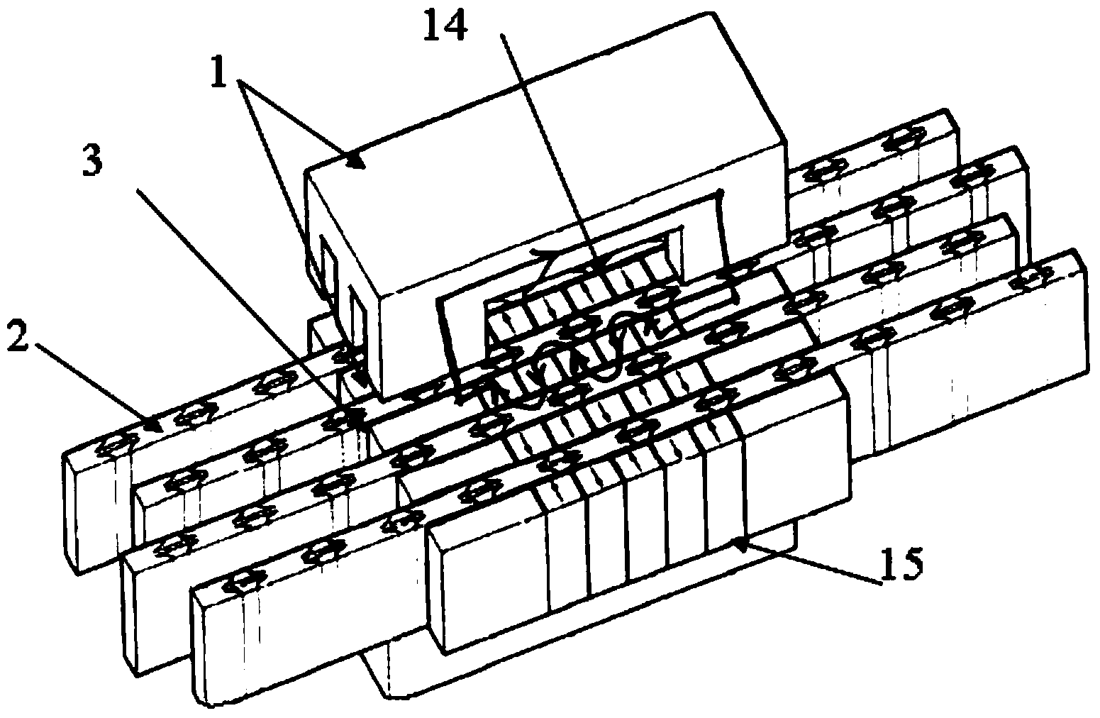
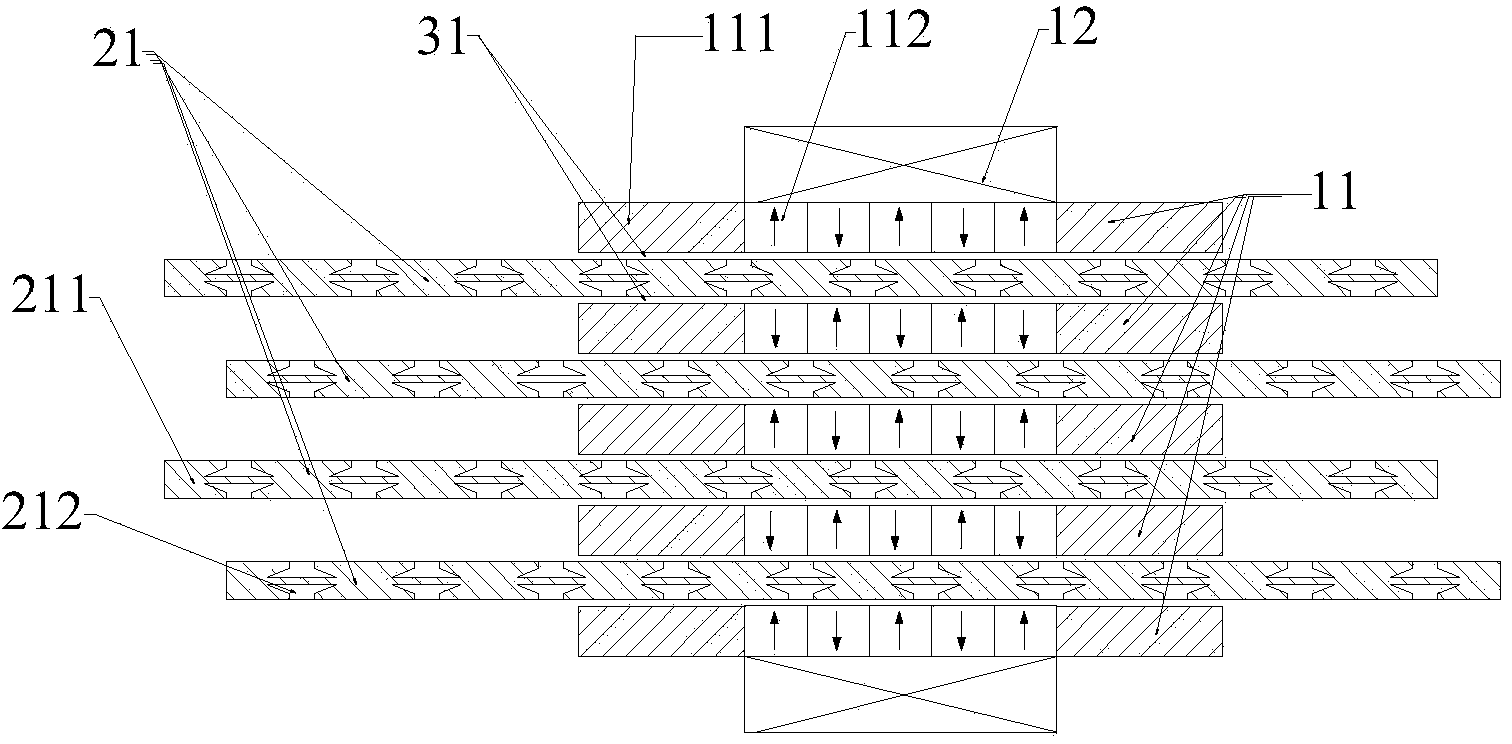
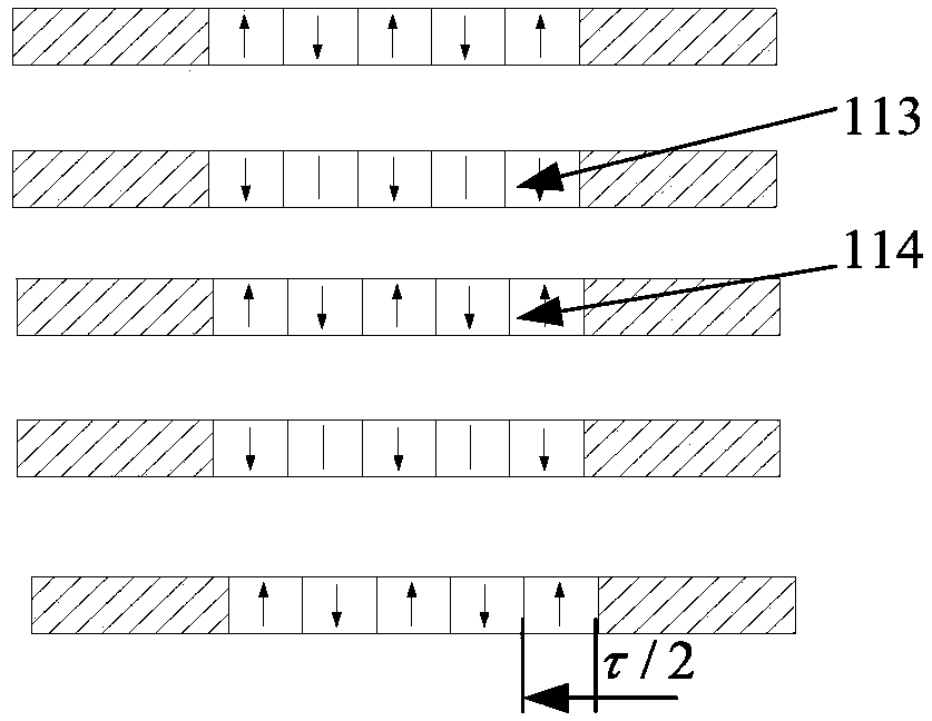
[0036] Such as figure 1 , figure 2 As shown, this embodiment is a single-phase motor 4 , including a primary component 1 , a secondary component 2 and (2n−2) air gaps 3 . The primary assembly 1 is composed of n primary units 11 and armature windings 12. The primary units 11 are arranged vertically and horizontally. Each primary unit has an array of (2m+1) permanent magnets 112 with staggered polarities. Each The width of the permanent magnet is a pole width τ / 2, and the magnetization direction of the permanent magnet is perpendicular to the plane of the air gap. For the permanent magnet array corresponding to the adjacent primary unit, the N pole permanent magnet 113 at the same horizontal position is opposite to the magnetization direction of the S pole permanent magnet 114, and the two ends of the permanent magnet array are provided with a square ring-shaped magnet core 111. The magnetic core 111 is connected into an integral ring structure via upper and lower beams. Two...
Embodiment approach 2
[0044] Such as Figure 8 As shown, the difference between the second embodiment and the first embodiment is that the secondary unit of the first embodiment is provided with a non-magnetic permeable groove 212 , and the secondary unit of the second embodiment is provided with a magnetic isolation bridge 213 . Similarly, the magnetic isolation bridge of the secondary unit of the motor in this embodiment can also be filled with a certain strength of lightweight material.
Embodiment approach 3
[0046] Such as Figure 9 As shown, the difference between the third embodiment and the first embodiment is that the first embodiment is a single-phase motor, and the third embodiment is a three-phase motor. The present embodiment is a three-phase motor, and the structures of the B-phase motor 5 and the C-phase motor 6 are exactly the same as that of the A-phase motor 4. The motor modules of each phase are arranged in the horizontal direction, and a magnetic core is arranged between every two-phase motors. The width of the permeable core in the horizontal direction S=(k±2 / 3)τ. The motor adopts a modular design for each phase, so that when a certain phase motor fails, other phases are not affected, which is conducive to realizing fault tolerance and improving the reliability of the motor.
PUM
 Abstract
Description
Claims
Application Information
 - R&D
- Intellectual Property
- Life Sciences
- Materials
- Tech Scout
- Unparalleled Data Quality
- Higher Quality Content
- 60% Fewer Hallucinations
Browse by: Latest US Patents, China's latest patents, Technical Efficacy Thesaurus, Application Domain, Technology Topic, Popular Technical Reports.
© 2025 PatSnap. All rights reserved.Legal|Privacy policy|Modern Slavery Act Transparency Statement|Sitemap|About US| Contact US: help@patsnap.com


