Underground continuous wall with prefabricated concrete-filled steel tube composite structure and method for constructing underground continuous wall

A technology of steel pipe concrete and underground diaphragm wall, which is applied in the direction of foundation structure engineering, excavation, sheet pile wall, etc. It can solve the problems of low strength at the joint of the wall, easy seepage at the joint, and great influence on the construction quality, so as to improve the durability High performance, high lateral stiffness, and the effect of improving connection performance

Active Publication Date: 2014-07-16
SOUTHEAST UNIV
View PDF5 Cites 4 Cited by
  • Summary
  • Abstract
  • Description
  • Claims
  • Application Information

AI Technical Summary

Problems solved by technology

However, the wall also has the following disadvantages: the construction quality is greatly affected by the soil layer, and quality problems such as wall shrinkage, collapse, leaking reinforcement, insufficient wall thickness, and "bulging" are prone to occur in complex strata; seepage and clamping are prone to occur at joints Quality problems such as sediment; when excavating the underground diaphragm wall with sediment,

Method used


Image

  • Underground continuous wall with prefabricated concrete-filled steel tube composite structure and method for constructing underground continuous wall
  • Underground continuous wall with prefabricated concrete-filled steel tube composite structure and method for constructing underground continuous wall
  • Underground continuous wall with prefabricated concrete-filled steel tube composite structure and method for constructing underground continuous wall

Examples


Embodiment Construction

[0040] Below in conjunction with accompanying drawing and embodiment mode, the patent of the present invention is described in further detail:

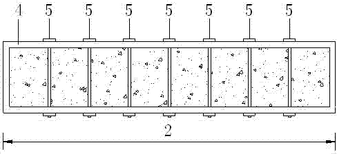
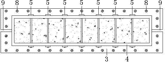
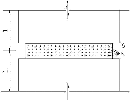
[0041] The underground diaphragm wall of the prefabricated concrete-filled steel tube composite structure of the present invention is: comprising several prefabricated connecting wall sections 1 sequentially connected vertically, the connecting wall sections include a composite steel tube concrete component 2 and an external cast-in-place box-type concrete structure 3, the The exterior of the steel pipe concrete composite member is a rectangular steel pipe 4, and the interior is wrapped with concrete. The steel pipes are provided with restraint rods 5 at a certain distance. The restraint rods are made of high-strength bolts. The grouting material forms a bonding area 7, prestressed steel strands 8 are set inside the box-shaped concrete structure, slots 9 are set in the middle or both sides of each end of the connecting wall section, co...


PUM


Abstract

The invention discloses an underground continuous wall with a prefabricated concrete-filled steel tube composite structure and a method for constructing the underground continuous wall. The underground continuous wall comprises a plurality of prefabricated connecting wall sections. The prefabricated connecting wall sections are vertically sequentially connected with one another and comprise concrete-filled steel tube composite members and external cast-in-place box-type concrete structures, rectangular steel tubes are arranged on the outsides of the concrete-filled steel tube composite members, concrete is arranged inside each concrete-filled steel tube composite member, the steel tubes are provided with binding bars at certain intervals, the binding bars are made of high-strength bolts, the protruded concrete-filled steel tube composite members of the wall sections are connected with one another by bolts, high-strength non-shrink grouting materials are poured in joints to form bond zones, prestressed steel strands are arranged inside the box-type concrete structures, slits are formed in the middle or two sides of each end of each connecting wall section, connecting steel plates are embedded among slit sections, slurry is poured in the wall sections after the wall sections are washed, and then the wall sections are integrally connected with one another. The underground continuous wall with the concrete-filled steel tube composite structure and the method have the advantages of good mechanical property, leakage resistance, reliability in connection, capability of implementing industrial production, and the like.

Description

technical field [0001] The invention relates to the field of design and construction of an underground diaphragm wall for building foundation pit engineering, in particular to an underground diaphragm wall of a prefabricated steel pipe concrete composite structure and a construction method for the underground diaphragm wall. Background technique [0002] The construction technology of underground diaphragm wall originated in Europe, and was popularized in western developed countries, the former Soviet Union and Japan in the 1950s and 1960s. In 1958, my country used this technology to build a dam cut-off wall. In the mid-1970s, this technology was applied to construction, coal mines and municipal industries. Due to its high rigidity, the underground diaphragm wall has the advantage of having little impact on the soil and structures around the foundation pit, and can be used as a retaining wall or the basement exterior wall of the main structure. [0003] What the underground...

Claims


Application Information

Patent Timeline
IPC IPC(8): E02D5/20E02D17/04
Inventor 金晓飞梁书亭朱筱俊张玉良
Owner SOUTHEAST UNIV
Why Eureka
Try Eureka