Composite cylinder cover

A cylinder head, composite technology, applied in the direction of cylinder head, cylinder, engine components, etc., can solve the problems of high manufacturing technology, process technology requirements, cooling effect of the nose bridge area, and complex structure of the cylinder head, so as to eliminate cylinder gaskets Ablation failure, improved cooling effect, and reduced assembly technical requirements

Active Publication Date: 2014-07-16
GUANGXI YUCHAI MASCH CO LTD
View PDF6 Cites 6 Cited by
  • Summary
  • Abstract
  • Description
  • Claims
  • Application Information

AI Technical Summary

Problems solved by technology

[0004] However, in the above technical solution, in order to ensure sealing, multiple cylinder head bolt holes are arranged around the cylinder bore, which will inevitably lead to complex internal structure of the cylinder head, difficult casting, high manufacturing cost, and the cooling effect on the nose bridge area will be affected.
In addition, ...

Method used


Image

  • Composite cylinder cover
  • Composite cylinder cover
  • Composite cylinder cover

Examples


Embodiment 1

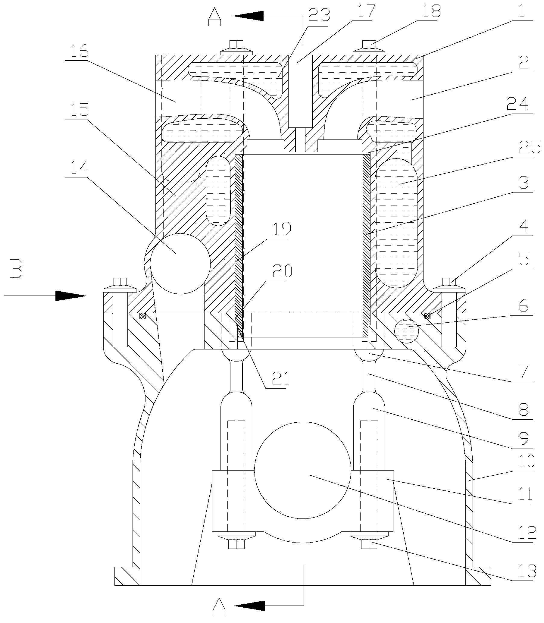
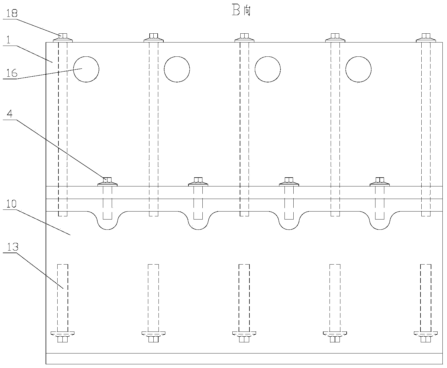
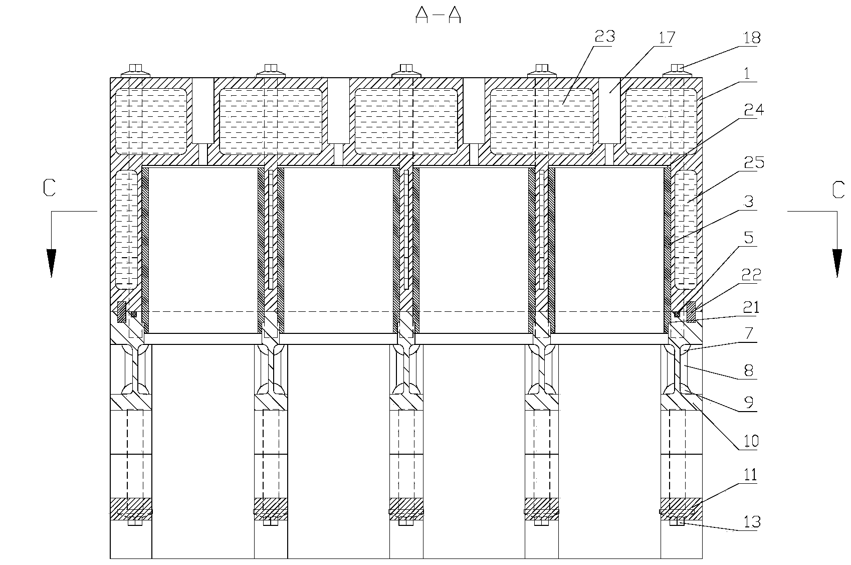
[0027] Such as figure 1 As shown, the composite cylinder head 1 according to the specific embodiment of the present invention can be directly installed on the crankcase 10 to form the body of the internal combustion engine, and the piston in the crankcase 10 can directly extend into the cylinder bore 19 to reciprocate. The cover 1 itself integrates all the intake passages 2, exhaust passages 16, fuel injector installation holes 17, cylinder head water jacket 23 and valve installation structure (not shown in the figure) of the traditional cylinder head. The valve installation structure can be an existing Have structure, be fixed on the top of this composite cylinder head 1 and get final product. Also integrated cylinder bore 19, cylinder bore water jacket 25, camshaft bore 14 and tappet bore 15 (see Figure 4 ). In this embodiment, the intake passage 2 and the exhaust passage 16 are arranged on both sides of the upper end of the cylinder head, and the fuel injector installati...

Embodiment 2

[0030] Such as figure 1 As shown, the body according to the specific embodiment of the present invention includes the composite cylinder head 1 and the crankcase 10 provided in Embodiment 1, the composite cylinder head 1 is installed on the upper end of the crankcase 10, and the upper end of the crankcase 10 is connected to the crankcase 10. The cylinder hole 19 on the composite cylinder head 1 is provided with a cylinder hole extension 20 at the corresponding position, and the cylinder hole 19 on the composite cylinder head 1 and the cylinder hole extension 20 form a body cylinder hole (not marked in the figure). The upper end surface of 10 is provided with a groove 5 for filling the sealant, and the groove 5 can also be arranged on the bottom end surface of the composite cylinder head 1, by filling the sealant in the groove 5 and the composite cylinder head 1 and the crankshaft The tight connection of the box 10 achieves the effect of sealing. As a preferred embodiment, a c...


PUM


Abstract

The invention discloses a composite cylinder cover and an engine body of an internal combustion engine. The composite cylinder cover is provided with a gas inlet channel, an exhaust channel and an oil injector installation hole, the composite cylinder cover is further integrated with a cam shaft hole, a tappet hole and a cylinder hole, the cam shaft hole and the tappet hole are formed in the same side of the composite cylinder cover, the cylinder hole is formed in the middle of the composite cylinder cover, and the composite cylinder cover can be directly installed on a crankcase so that a piston can directly extend into the cylinder hole and moves in a reciprocating mode. The engine body of the internal combustion engine comprises the composite cylinder cover and the crankcase. By means of the composite cylinder cover and the engine body of the internal combustion engine, the faults of cylinder gasket pushing and cylinder gasket ablation of a traditional cylinder cover structure can be fundamentally avoided, meanwhile, the complex structure of a cooling water cavity in the cylinder cover is changed, the structure is simplified, and manufacturing requirements are low.

Description

technical field [0001] The invention relates to the field of internal combustion engines, in particular to a composite cylinder head. Background technique [0002] The cylinder head is a key component of a traditional internal combustion engine, and together with the cylinder block and cylinder liner, it forms the basic skeleton of the internal combustion engine. Specifically, the cylinder head is installed on the cylinder block through cylinder head bolts, and the cylinder liner is installed in the cylinder bore of the cylinder block (the cylinder bore of some internal combustion engines is used to directly install the piston). In the combustion chamber, the piston reciprocates in the cylinder liner, and the gas distribution mechanism and cover are installed on the cylinder head. The traditional cylinder head is generally a box structure. The box has air passages, valve installation structures, cylinder head bolt hole columns, oil hole columns, air hole columns and water j...

Claims


Application Information

Patent Timeline
IPC IPC(8): F02F1/36
Inventor 沈捷覃文王利民覃壮革向本杰粟荣锦
Owner GUANGXI YUCHAI MASCH CO LTD
Why Eureka
Try Eureka