Optical fiber sensing type continuous automatic weighing system and method free of speed sensors

A technology of speed sensor and optical fiber sensing, which is applied in the field of continuous automatic weighing technology, can solve the problems of speed detection description, not in the same place, change, etc., so as to ensure feasibility and reliability, improve stability and reliability, and reduce The effect of the failure rate

Inactive Publication Date: 2014-07-16
WUHAN UNIV OF TECH
View PDF8 Cites 4 Cited by
  • Summary
  • Abstract
  • Description
  • Claims
  • Application Information

AI Technical Summary

Problems solved by technology

At present, the related patents of optical fiber sensing technology for continuous automatic weighing are: Differential strain type optical fiber Bragg grating suspension belt scale, the patent number is CN201020103073.0, this patent utilizes optical fiber grating sensing technology, adopts The beam structure realizes material weighing, but does not provide any description for speed detection
[0004] For the detection of conveying speed, the current method is to install a speed sensor on the material conveying equipment. However, the installation position of the speed sensor and the weighing device is not at the same place, which makes it difficult to maintain the speed detection result and

Method used


Image

  • Optical fiber sensing type continuous automatic weighing system and method free of speed sensors
  • Optical fiber sensing type continuous automatic weighing system and method free of speed sensors
  • Optical fiber sensing type continuous automatic weighing system and method free of speed sensors

Examples


Embodiment Construction

[0027] The present invention will be further described below in conjunction with specific examples and accompanying drawings.

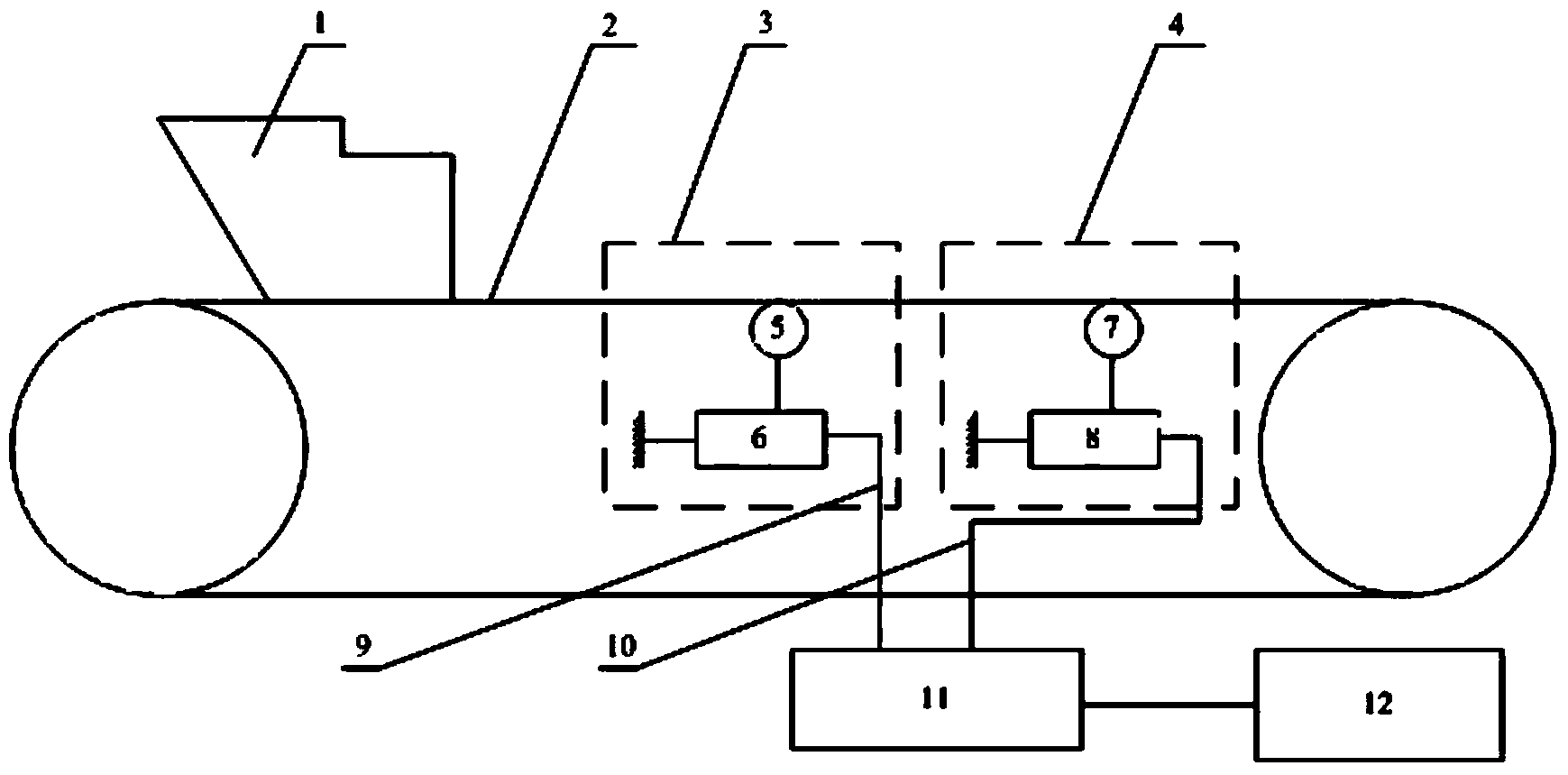
[0028] figure 1 It is a structural schematic diagram of an embodiment of the present invention, which includes a first fiber grating sensing weighing device 3, a second fiber grating sensing weighing device 4, a fiber grating demodulator 11 and a computer 12; wherein the first fiber grating sensing Sense weighing device 3 and the structure of the second fiber grating sensing weighing device 4 are identical, respectively comprise the force transmission part (the first force transmission part 5 among the figure) that is used to transmit the weight of the material on the material conveyor belt and the second force transmission part 7) and the fiber grating strain sensor (in this embodiment, the first fiber grating strain sensor 6 and the second fiber grating strain sensor 8 in the figure) for converting the weight of the material into an optical signal, ...


PUM


Abstract

The invention provides an optical fiber sensing type continuous automatic weighing system free of speed sensors. The optical fiber sensing type continuous automatic weighing system free of the speed sensors comprises a first fiber bragg grating sensing weighing device, a second fiber bragg grating sensing weighing device, a fiber bragg grating demodulation instrument and a computer, wherein the first fiber bragg grating sensing weighing device and the second fiber bragg grating sensing weighing device respectively comprise a force transmission component used for transmitting the weight of materials on a material conveying belt, and a fiber bragg grating strain sensor used for converting the weight of the materials into an optical signal, the force transmission components are arranged at the front end and the rear end of the material conveying belt respectively, the output end of each fiber bragg grating strain sensor is connected with the fiber bragg grating demodulation instrument through a transmission optical path, and the two paths of optical signals are converted into digital signals through the fiber bragg grating demodulation instrument and are then transmitted to the computer. According to the optical fiber sensing type continuous automatic weighing system free of the speed sensors, all on-site detection elements are of the optical fiber type, electric sensing elements are eliminated completely, and thus the weighing system can be adapted to severe monitoring environments; due to the fact that a measurement unit is omitted, an error source is eliminated, and the fault rate of the weighing system is decreased.

Description

technical field [0001] The invention relates to optical fiber sensing technology and dynamic weighing instrument technology, in particular to a continuous automatic weighing technology. Background technique [0002] The function of the continuous automatic weighing system is used for the measurement in the process of conveying materials, and it is widely used in the fields of grain, coal, mining, metallurgy, building materials, and pharmaceuticals. The continuous automatic weighing system needs to have two basic functions, one is the detection of the continuous load of the material, and the other is the detection of the conveying speed. [0003] At present, the continuous load of materials in continuous automatic weighing systems at home and abroad is basically detected by electrical sensing elements. It performs poorly under harsh monitoring conditions. When it is used in a complex monitoring environment for a long time, it is prone to failures such as zero drift, which gr...

Claims


Application Information

Patent Timeline
IPC IPC(8): G01G11/00
Inventor 潘建军李维来李汉福周卫东刘捷庞锦鲁晓珊
Owner WUHAN UNIV OF TECH
Why Eureka
Try Eureka